Bonding structure of metal member and composite-material member

a technology of composite materials and metal parts, applied in the direction of non-disconnectible pipe joints, rigid containers, vessel geometry/arrangement/size, etc., can solve the problems of tank not being entirely made of composite materials, affecting the bonding performance of metal parts, and affecting the bonding performance of composite materials, etc., to achieve the effect of reducing the energy release rate of the adhesive bonding surface, preventing debonding, and reducing the stiffness

Inactive Publication Date: 2012-12-27
JAPAN AEROSPACE EXPLORATION AGENCY
View PDF12 Cites 8 Cited by
  • Summary
  • Abstract
  • Description
  • Claims
  • Application Information

AI Technical Summary

Benefits of technology

[0037]According to the present invention, in a bonding structure of a metal member and a composite-material member, with an adhesive bonding portion between the metal member and the composite-material member, the metal member is provided with a slit extending along an adhesive bonding surface between the metal member and the composite-material member to form a thin-walled portion between the adhesive bonding surface and the slit, so that a region of the metal member on the side of the adhesive bonding surface is reduced in stiffness. This makes it possible to significantly reduce an energy release rate in the adhesive bonding surface between the metal member and the composite-material member to prevent debonding therebetween.
[0038]According to the present invention, in a tank comprising a composite-material outer shell and a metal mouthpiece having a tubular portion, wherein the mouthpiece is connected to the outer shell at an opening provided in the outer shell, a slit is provided in an outer peripheral region of the tubular portion of the mouthpiece of the tank, to reduce a thickness of a region of the mouthpiece adjacent to an adhesive bonding surface between the composite-material outer shell and the tubular portion of the mouthpiece, i.e., the tubular portion of the mouthpiece is provided with a slit extending along an adhesive bonding surface between the composite-material outer shell and the tubular portion of the mouthpiece of the tank, to form a thin-walled portion between the adhesive bonding surface and the slit, so that a region of the tubular portion of the mouthpiece on the side of the adhesive bonding surface is reduced in stiffness. This makes it possible to significantly reduce an energy release rate in the adhesive bonding surface between the composite-material outer shell and the metal mouthpiece to prevent debonding therebetween.
[0039]In addition, differently from the technique disclosed in the Patent Document 1 in which, for an inner shell in which a peripheral portion around an opening of a tank is made of metal and an outer shell made of composite material, a fixing means is provided in the peripheral portion around the opening to constrain the inner shell and the outer shell with respect to each other, there is no need for fabrication of a screw hole, and a fixing component. This makes it possible to facilitate fabrication, and reduce the number of components to facilitate a reduction in weight.
[0040]According to the present invention, in a satellite body where a composite-material thrust tube and at least one of a top panel and a bottom panel are joined by a metal bracket, the metal bracket is provided with a slit extending along an adhesive bonding surface between the metal bracket and the composite-material thrust tube, to form a thin-walled portion between the adhesive bonding surface and the slit, so that a region of the metal bracket on the side of the adhesive bonding surface is reduced in stiffness. This makes it possible to significantly reduce an energy release rate in the adhesive bonding surface between the thrust tube and the metal bracket to prevent debonding between the thrust tube and the metal bracket.
[0041]According to the present invention, in a rocket where a composite-material skin plate constituting a tail fin, and a rocket body, are joined together by a metal fitting joined to the rocket body, the metal fitting is provided with a slit extending along an adhesive bonding surface between the metal fitting and the composite-material skin plate of the tail fin, to form a thin-walled portion between the adhesive bonding surface and the slit, so that a region of the metal fitting on the side of the adhesive bonding surface is reduced in stiffness. This makes it possible to significantly reduce an energy release rate in the adhesive bonding surface between the skin plate of the tail fin and the metal fitting to prevent debonding between the skin plate of the tail fin and the metal fitting.

Problems solved by technology

Generally, in an adhesive bonding portion between a metal member and a composite-material member, material characteristics, such as coefficient of thermal expansion and stiffness, change discontinuously, which causes a situation where stress concentration is likely to occur therein, resulting in debonding.
Thus, the occurrence and development of the debonding between the metal member and the composite-material member lead to fracture of a structure including the adhesive bonding portion between the metal member and the composite-material member.
Thus, a tank cannot be entirely made of composite material, i.e., it inevitably has an adhesive bonding portion between a metal member and a composite-material member.
Generally, in the adhesive bonding portion between the metal member and the composite-material member, material characteristics, such as coefficient of thermal expansion and stiffness, change discontinuously, which causes a situation where stress concentration is likely to occur therein, resulting in debonding, as mentioned above.
Thus, the occurrence and development of the debonding between the metal member and the composite-material member lead to fracture of the tank.
Thus, if such a tank is increased in internal pressure and / or size in future, it is predicted that debonding between the metal member and the composite-material member also becomes a problem.
In these bonding structures, debonding between a metal member and a composite-material member also becomes a problem.

Method used


Image

  • Bonding structure of metal member and composite-material member
  • Bonding structure of metal member and composite-material member
  • Bonding structure of metal member and composite-material member

Examples


first embodiment

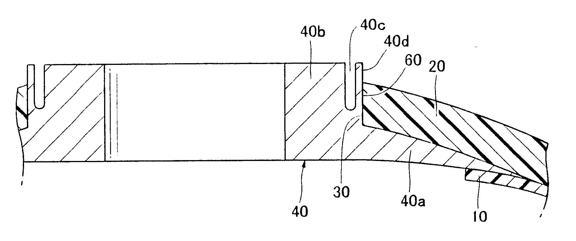
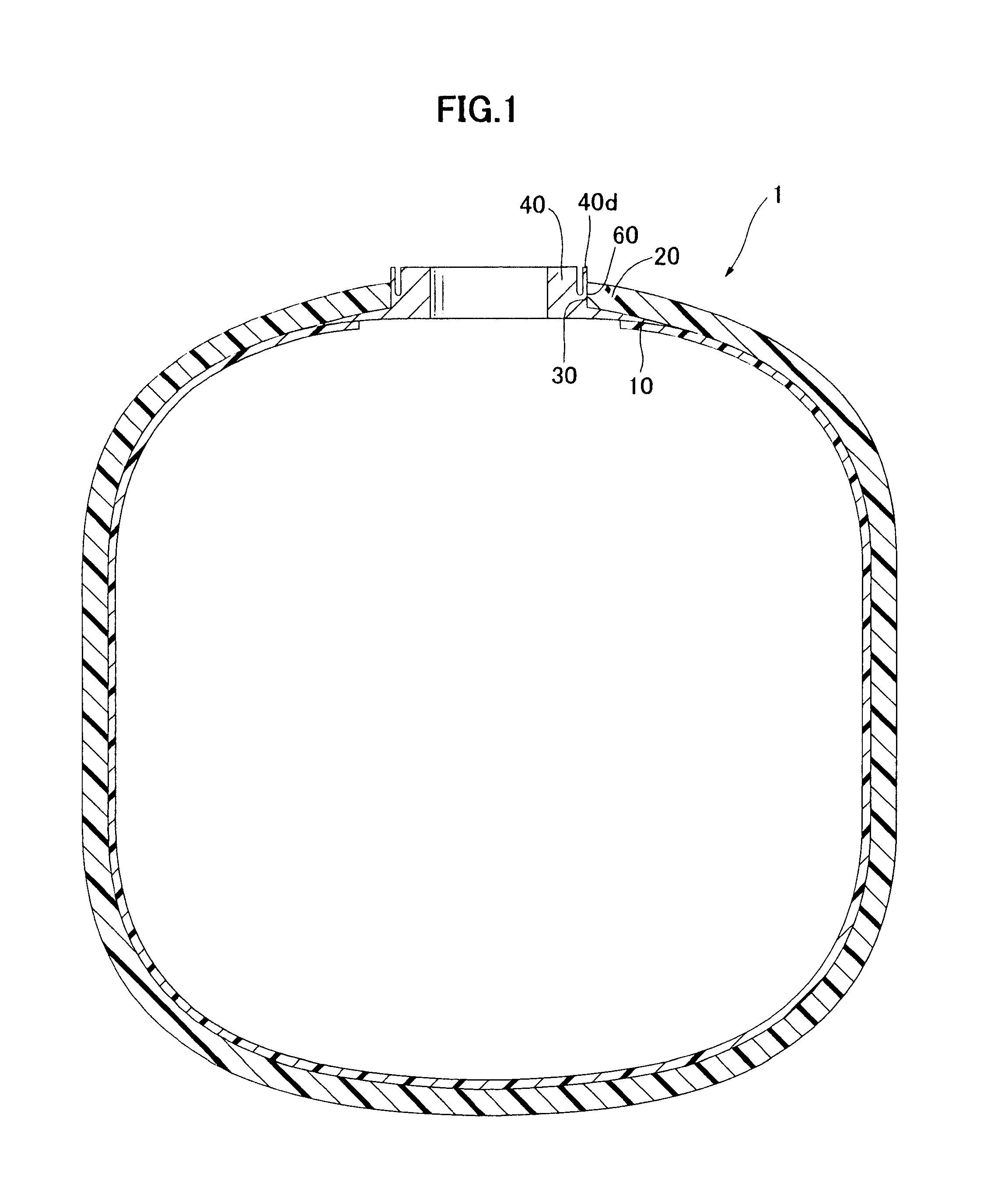
[0055]FIG. 1 is a sectional view of a tank 1 according to a first embodiment of the present invention, and FIG. 2 is a sectional view of a mouthpiece region of the tank 1. As illustrated in FIG. 1, the tank 1 comprises an inner shell 10, an outer shell 20 covering the inner shell 10, and a mouthpiece 40 connected to the outer shell 20 through an opening 30 provided in the outer shell 20. In FIG. 1, the opening 30 is provided in a top portion of the tank 1. Additionally, another opening30 and another mouthpiece 40 may be provided in a bottom portion of the tank 1.

[0056]The inner shell 10 is formed of a liner made of resin having a high gas barrier capability, such as liquid-crystal polymer and adapted to prevent leakage of an internal fluid.

[0057]The mouthpiece 40 is made of metal, such as titanium, and formed in a cylindrical shape. The mouthpiece 40 has a flange portion 40a formed at an end thereof on an inner side of the tank, and a tubular portion 40b standing upwardly from the f...

second embodiment

[0076]FIGS. 7 and 8 are sectional views of a mouthpiece region of a tank 1 according to a second embodiment of the present invention. In the second embodiment, any configuration other than a mouthpiece 40 is the same as that in FIG. 1. In FIGS. 7 and 8, an element or component corresponding to that in FIGS. 1 and 2 is assigned with the same reference numeral or code, and the description of an element or component equivalent to that in the first embodiment will be omitted.

[0077]The second embodiment is intended to, when it is difficult to fabricate a slit 40c from an end of a tubular portion 40b of the mouthpiece 40 on an outer side of the tank due to a shape of the mouthpiece 40, fabricate the slit 40c from an outer peripheral surface of the tubular portion 40b to obtain the same effects as those in the first embodiment. For example, as illustrated in FIG. 7, a slit 40c is formed obliquely with respect to the outer peripheral surface of the tubular portion 40b, or an adhesive bondin...

third embodiment

[0082]FIG. 9 is a sectional view of a satellite body 101 according to a third embodiment of the present invention. As illustrated in FIG. 9, a cylindrical-shaped CFRP thrust tube 120 is disposed in the middle of an internal space of the satellite body 101, and a circular-shaped top panel 102 and a circular-shaped bottom panel 104 are attached, respectively, to a top and a bottom of the thrust tube 120 by metal brackets 140. Further, a cylindrical-shaped exterior panel 106 is attached to the top panel 102 and the bottom panel 104 to define an outer surface of the satellite body 101. In this structure, the thrust tube 120 supports the entire load of a satellite.

[0083]FIG. 10 is a sectional view of a joining region between the thrust tube 120 and the upper panel 102 which is an enlarged view of the section A in FIG. 9. As illustrated in FIG. 10, the thrust tube 120 and a vertical piece of the metal bracket 140 are adhesively bonded together through an adhesive bonding surface 160, and ...


PUM

PropertyMeasurementUnit
diameteraaaaaaaaaa
lengthaaaaaaaaaa
operating pressureaaaaaaaaaa

Abstract

Provided is a bonding structure of a metal member and a composite-material member which comprises a composite-material member and a metal member adhesively bonded to the composite-material member through an adhesive bonding surface therebetween. The metal member has a slit extending along the adhesive bonding surface to form a thin-walled portion between the adhesive bonding surface and the slit.

Description

CROSS-REFERENCE TO RELATED APPLICATIONS[0001]This patent application is a continuation of International Application No. PCT / JP2010 / 069265, filed Oct. 29, 2010, entitled JOINT STRUCTURE FOR METAL MEMBER AND COMPOSITE MEMBER, which claims priority to Japanese Patent Application No. 2009-249822, filed Oct. 30, 2009.TECHNICAL FIELD[0002]The present invention relates to a bonding structure of a metal member and a composite-material member, and more specifically to a bonding structure of a metal member and a composite-material member, with an adhesive bonding portion between the metal member and the composite-material member.BACKGROUND ART[0003]Generally, in an adhesive bonding portion between a metal member and a composite-material member, material characteristics, such as coefficient of thermal expansion and stiffness, change discontinuously, which causes a situation where stress concentration is likely to occur therein, resulting in debonding. Thus, the occurrence and development of th...

Claims


Application Information

Patent Timeline
Patent Type & Authority Applications(United States)
IPC IPC(8): B65D6/40B32B1/00B32B3/30
CPCF17C1/16Y10T428/12229F17C1/04F17C2209/227F17C2201/0109F17C2201/0123F17C2201/0161F17C2203/0604F17C2203/0619F17C2203/0636F17C2203/0663F17C2205/0305F17C2205/0397F17C2223/0161F17C2260/011F17C2260/013F17C2260/036F17C2260/046F17C2270/0168F17C2270/0189F17C2270/0197B64G1/402Y10T403/47Y10T428/12389F17C1/02F17C2203/066B64G1/22F17C1/00F17C13/00F17C2203/011F17C2205/0302
Inventor TAKEUCHI, SHINSUKESATO, EIICHI
Owner JAPAN AEROSPACE EXPLORATION AGENCY
Why Eureka
Try Eureka