Integrated imaging system

Inactive Publication Date: 2012-12-27
JOS SCHNEIDER OPTISCHE WERKE AKTIENGESELLSCHAFT
View PDF3 Cites 20 Cited by
  • Summary
  • Abstract
  • Description
  • Claims
  • Application Information

AI Technical Summary

Benefits of technology

[0024]One advantageous embodiment of the proposed solution also makes it possible for the focal length of the imaging system to be continuously adjustable by means of an electrical driving of the at least one optical element.
[0033]The functioning of a piezo-actuator is based on piezoelectricity (also called piezoelectric effect). Piezoelectricity describes the change in electrical polarization and thus the occurrence of an electrical voltage at certain solid bodies when they are elastically deformed (direct piezoelectric effect). Conversely, certain materials deform when an electrical voltage is applied (inverse piezoelectric effect). As a result of the directed deformation of a piezoelectric material, microscopic dipoles form within the elementary cells. Summation by way of the associated electric field in all of the elementary cells of the crystal results in a macroscopically measurable electrical voltage. Conversely, by applying an electrical voltage it is possible to achieve a deformation of a component composed of piezoceramic.
[0035]A liquid lens generally consists of an aqueous solution and an oil. The two liquids have different refractive indices and do not mix. A liquid lens can be constructed, for example, in such a way that the two liquids are situated in a short tubular container, at the ends of which transparent end caps are arranged. One of the end caps and the wall interior surfaces of the tubular container are provided with a water-repellent coating. This has the effect that the aqueous solution collects at the non-coated end of the tube and collects there to form a hemispherical mass. This hemispherical mass forms a lens-shaped body, which also has the optical properties of a lens, for example of a convex lens.
[0037]Consequently, the lens form can be controlled electrically. The applied electric field reduces the water-repellant effect of the coating. As a result, the aqueous solution wets the sidewalls of the tubular container to a greater extent and the radius of curvature of the curved surface between the two liquids and the focal length of the lens change when the voltage at the electrodes of the liquid lens is switched on or off. By means of the change (increase or decrease) it is even possible to obtain an alteration of the lens form from convex to plane or concave.
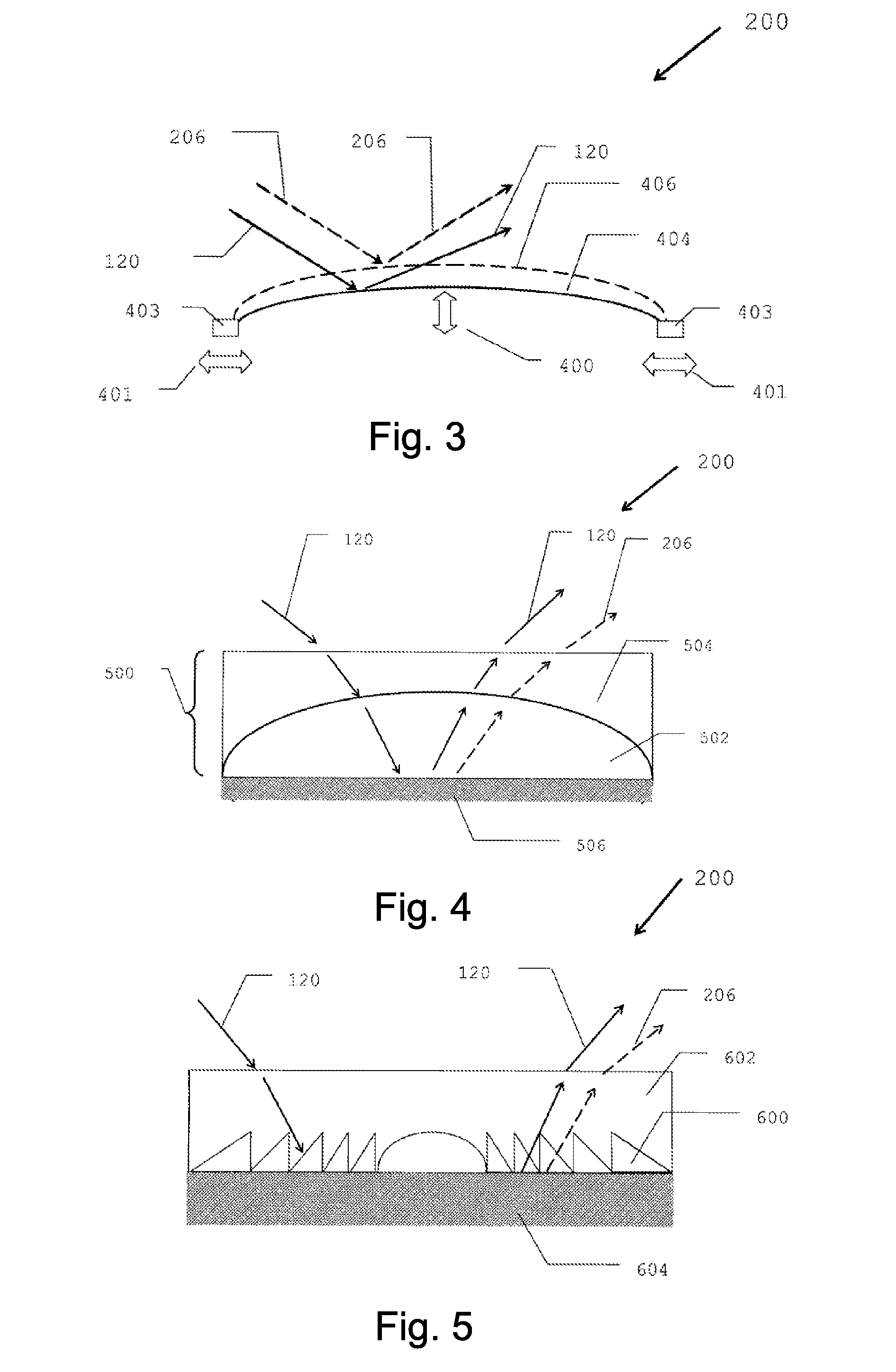
[0051]A Fresnel lens or more precisely a Fresnel stepped lens is an optical lens in which weight and volume are reduced by comparison with a customary optical lens with the same diameter and the same focal length. This has an effect particularly in the case of lenses having a short focal length, which in a normal form are very thick and heavy. In Fresnel lenses, the volume is reduced by division into ring-shaped regions. The thickness is reduced in each of these regions, such that the lens acquires a series of ring-shaped steps. Since light is refracted only when passing through the lens surfaces, the angle of refraction is not dependent on the thickness, but rather only on the angle between the two surfaces. The lens maintains its focal length, but the imaging quality is impaired by the stepped structure. Fresnel lenses are generally used where the weight of the lenses is crucial and the imaging quality is of secondary importance.
[0052]If a Fresnel lens is covered with a liquid crystal, then the refractive index of the liquid crystal can be electrically switched. It can be switched e.g., such that, in one switching state, there is a jump in refractive index between the material of the Fresnel lens and the liquid crystal, as a result of which the Fresnel lens has an effect. In the other switching state, the refractive index difference can disappear, such that the Fresnel lens does not have an effect. In this way, the effect of the Fresnel lens can be switched on and off.

Problems solved by technology

The constantly increasing requirements made in respect of the flattest possible construction of the modules impose limits, however, for the previously used devices and systems, particularly also with regard to the variability of the focal length.
This has an effect particularly in the case of lenses having a short focal length, which in a normal form are very thick and heavy.
The lens maintains its focal length, but the imaging quality is impaired by the stepped structure.
Refraction in a lens or a prism always leads to dispersion, i.e., color splitting.

Method used


Image

  • Integrated imaging system
  • Integrated imaging system
  • Integrated imaging system

Examples


Embodiment Construction

[0064]FIG. 1 schematically shows an imaging system 100′ corresponding to the prior art having a fixed focal length. (primed numbers, i.e., in the form “nn′”, are used to distinguish elements of this prior art apparatus from similarly numbered elements in the subsequently described embodiments of the present invention.) The system 100′ shown has a front side 102′ and a rear side 104′. A front lens 106′, two optical elements 108′, 110′, and an image sensor 112′ are situated at the front side 102′. An optical element 114′, an optical element 116′, and an optical element 118′ are arranged opposite at the rear side 104′ of the system 100′ shown. The optical elements 108′, 110′, 114′, 116′ and 118′ can have refractive or diffractive, transmissive or reflective optical properties.

[0065]The beam path 120 runs from the object (not illustrated) through the front lens 106′ to the first optical element 114′, further via the second optical element 108′, the third optical element 116′, the fourth...


PUM


Abstract

An imaging system having a front side and rear side enveloping a light transmitting space formed therebetween A front lens situated on the front side forms a portal through which light from an object enters into the light transmitting space wherein at least one optical element composed of glass or elastic material, liquid lenses or liquid crystal elements, and an image sensor are positioned to develop a folded beam path between the front lens and the image sensor, and a real image of the object on the image sensor. Electrically driving at least one optical element enables alteration of the focal length within the system in a manner switchable between at least two values. The change in focal length is realized with the aid of electrically controlled piezo-actuators or by an electric field applied to at least one variable optical element.

Description

CROSS REFERENCE TO RELATED APPLICATION[0001]This application is related to pending U.S. application Ser. No. 13 / 579,909 filed Aug. 17, 2012 entitled “Imaging System” invented by Lingli WANG of Bad Kreuznach, Germany, the disclosure of which is expressly incorporated herein by reference.FIELD OF THE INVENTION[0002]The invention relates to an imaging system for imaging an object onto an image sensor.PRIOR ART[0003]The trend in the development of optical modules, in particular for mobile radio devices (cell phones), is increasingly toward a very flat design. In this case, increasingly a construction is preferred in which a plurality of optical elements having selected refractive, diffractive, transmissive or reflective properties are combined with one another in order to realize the desired beam path and to produce an imaging on an image sensor (see FIG. 1; or e.g., J. Jahns: “Integrated optical imaging system”, Appl. Opt. 29 (1990) 1998).[0004]The constantly increasing requirements ma...

Claims


Application Information

Patent Timeline
IPC IPC(8): H04N5/225G02B15/00G02B3/14
CPCG02B3/14G02B26/005G02B15/00G02B13/009G02B13/00G02B26/02
Inventor WANG, LINGLI
Owner JOS SCHNEIDER OPTISCHE WERKE AKTIENGESELLSCHAFT
Why Eureka
Try Eureka