Assembly to perform imaging on rodents

a technology for performing imaging and rodents, which is applied in the field of assembly to perform imaging on rodents, can solve the problems of increasing animal stress, difficult to find the correct pressure to securely fix the animal, and unable to eliminate the movement of the remaining animal, so as to achieve the optimal signal-to-noise ratio (snr) and eliminate the effect of remaining animal movemen

Inactive Publication Date: 2012-12-27
RAPID BIOMEDIZINISCHE GERATE RAPID BIOMEDICAL
View PDF28 Cites 21 Cited by
  • Summary
  • Abstract
  • Description
  • Claims
  • Application Information

AI Technical Summary

Benefits of technology

[0010]Provided is a restraining assembly for an anaesthetized rodent (rats or mice or other) in combination with a split array coil for magnetic resonance imaging (MRI). In one example embodiment, the restraining assembly is designed for imaging the complete head, or alternatively the complete heart, of the animal. The assembly allows adjustment so that the animal can be imaged in an optimum position and so that the coil size can be adjusted to the particular size of the animal's head for maximum filling factor and optimum signal-to-noise-ratio (SNR). The positioning can be reproduced in later experiments. The assembly further includes parts that largely eliminate remaining animal movement and so supress motion artefacts during an MR experiment.

Problems solved by technology

Anesthetized animals, and in particular rodents, often cannot hold their body temperature at desired temperatures during such procedures, potentially leading to stress on the animal.
However, it is often difficult to find the correct pressure to securely fixate the animal and lock it securely in one position and not harm the animal (e.g. perforate its ear drums).
Due to the set-up from both sides of the animal's head, it is relatively time consuming to lock the animal head and to position it in the centre of the assembly, and so poses additional stress to the animal.
The stereotactic set-up with ear pins also consumes valuable space and so limits the coil's filling factor.
However, a small positioning error can lead to large changes in the signal intensity, and affect the measurement.
So both, the penetration depth and the homogeneity of the surface coil are rather poor.

Method used


Image

  • Assembly to perform imaging on rodents
  • Assembly to perform imaging on rodents
  • Assembly to perform imaging on rodents

Examples


Embodiment Construction

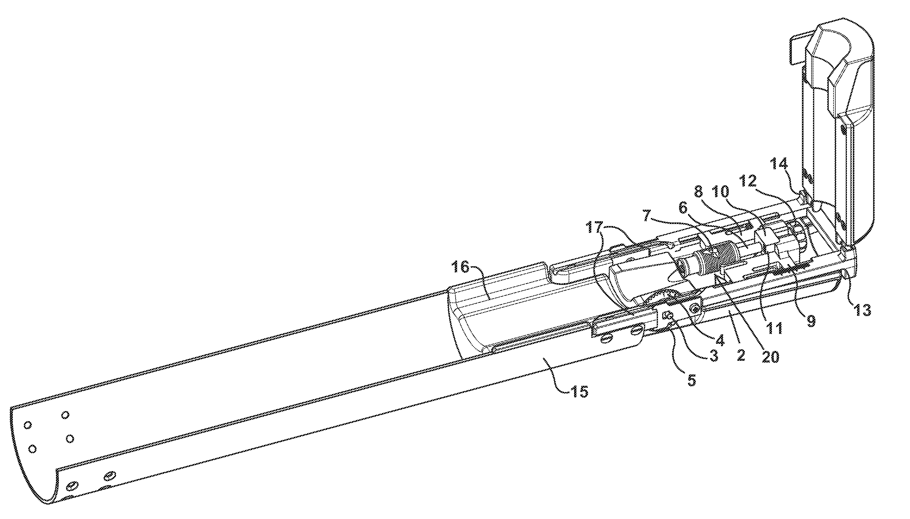
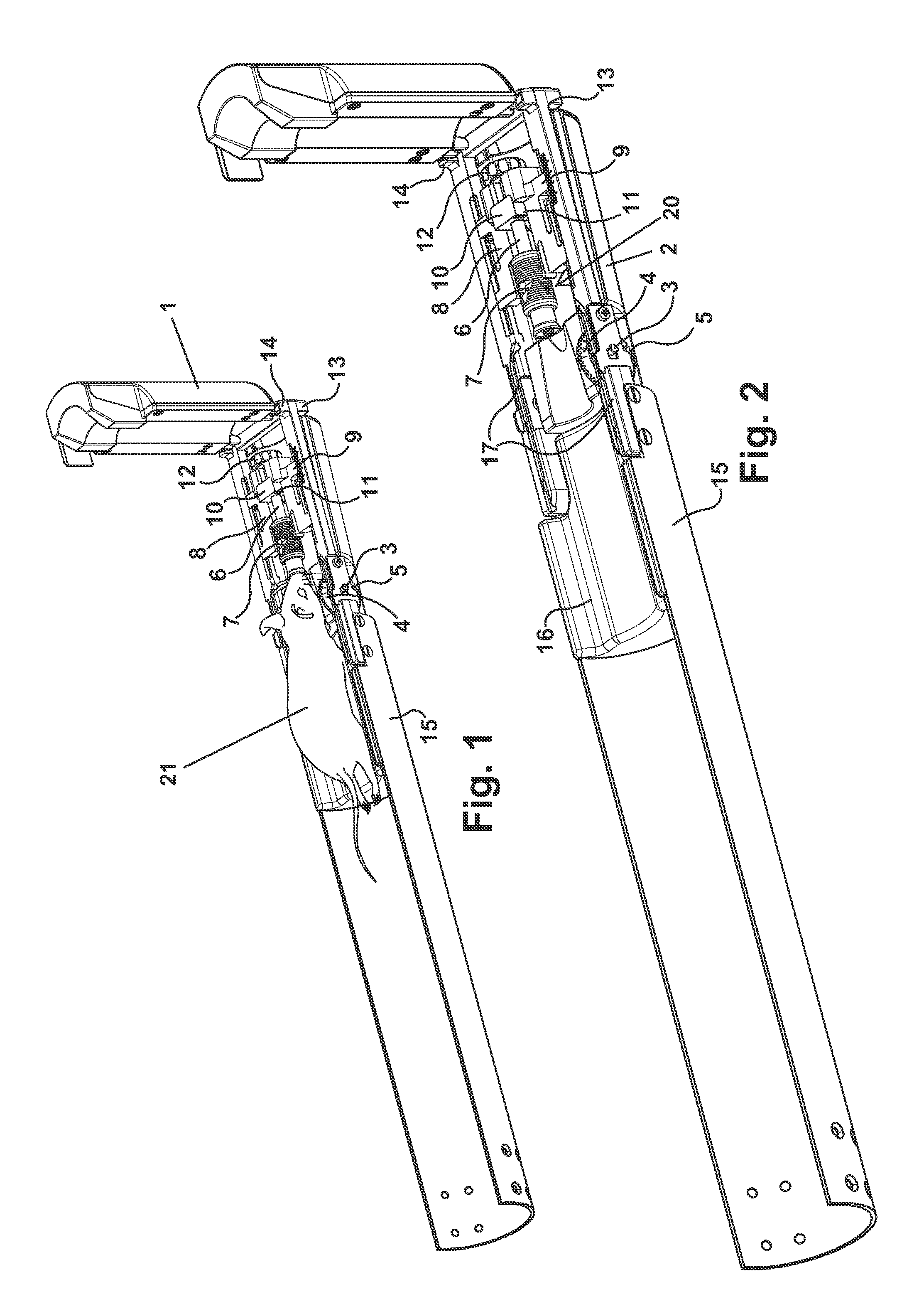
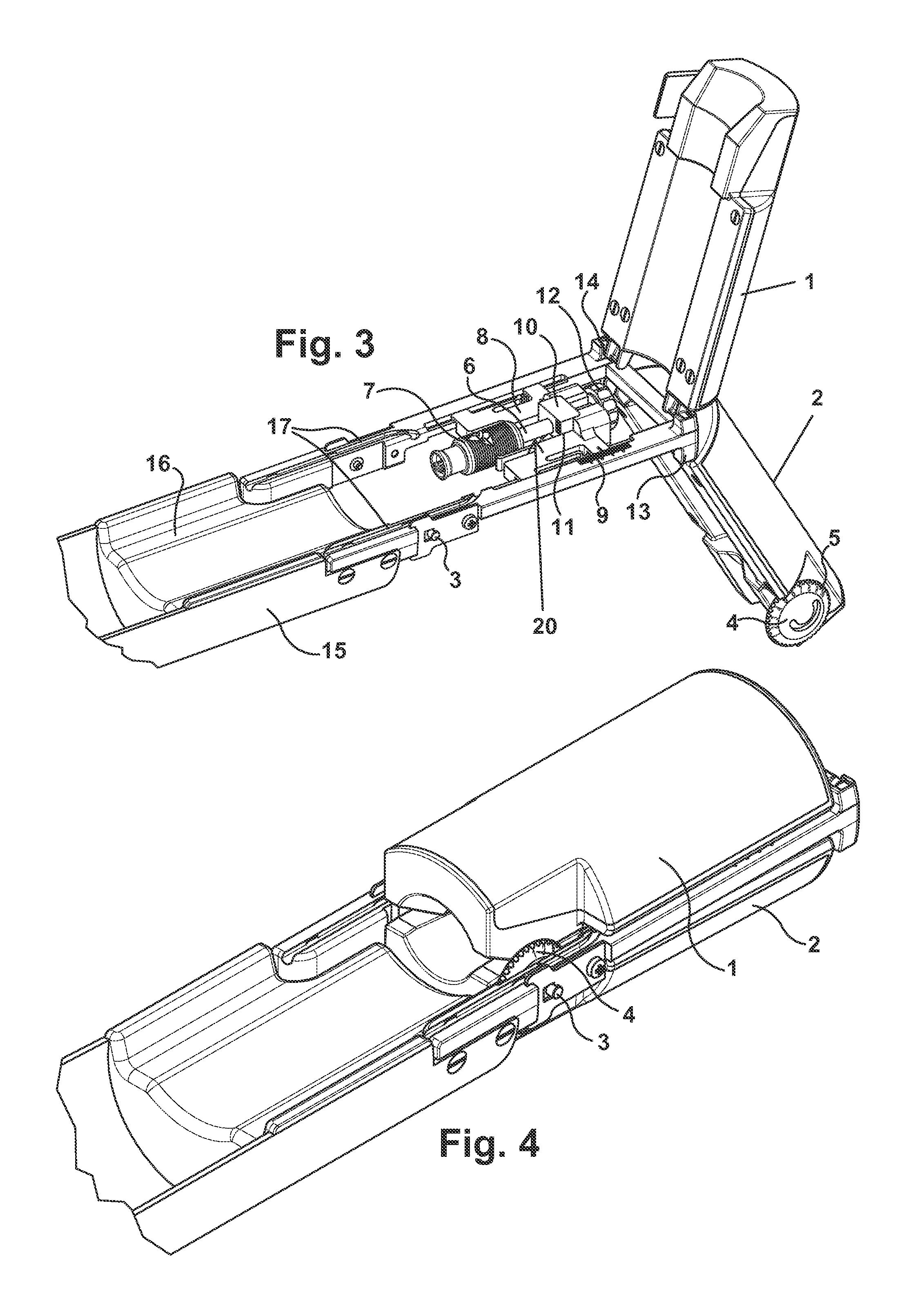
[0027]FIGS. 1-7 provide a first example embodiment of an imaging assembly for imaging a mouse, with the assembly comprising a combined array coil including a top part 1 and a bottom part 2. The coil parts contain the electrical coils for performing the imagings. The two coil parts 1, 2 can be separated from the coil holder 17 (see FIGS. 3 & 17) to allow for a correct sample positioning. Each of the coil parts 1, 2 can operate as a separate channel for the imaging signal(s). The assembly parts can be adjusted to the size of the sample, so that the animal head is fixed in position (e.g., using the gas mask 7 and the tooth bar 6) and also to obtain a maximum filling factor and optimum SNR.

[0028]This example assembly is for neuroimaging of an anesthetized, in the case of this particular example, for a mouse. The animal is held in position by the use of three mechanisms that are very quickly implemented and minimise the set-up time and so reduce the stress for the animal. This assembly a...


PUM


Abstract

An imaging device for imaging an anaesthetized animal such as a rodent (rats or mice or other animals), with the device having a split array coil capable of providing at least two channels for use in a restraining assembly with animal bed for magnetic resonance imaging (MRI) the animal in real-time in a non-destructive manner.

Description

CROSS-REFERENCES TO RELATED APPLICATIONS[0001]This application is a continuation-in-part of U.S. patent application Ser. No. 13 / 464,063, filed on May 4, 2012, incorporated herein by reference, which claims the benefit of U.S. provisional application Ser. No. 61 / 483,256 filed on May 6, 2011, incorporated herein by reference, and also claims the benefit of U.S. provisional application Ser. No. 61 / 483,281 filed on May 6, 2011, and also incorporated herein by reference.BACKGROUND OF THE INVENTION[0002]This application relates generally to an animal holding device for holding an animal during an imaging operation.[0003]More specifically, this application relates to an apparatus and method including a restraining assembly for an anaesthetized rodent (rats or mice or other) in combination with a split array coil for magnetic resonance imaging (MRI) the animal in real-time in a non-destructive manner.[0004]Rodents and other laboratory animals are often used for testing purposes. Such testin...

Claims


Application Information

Patent Timeline
Patent Type & Authority Applications(United States)
IPC IPC(8): A61B5/055A61M16/06
CPCA61B6/0407A61B6/4417A61B5/0555A61B6/508A01K1/0613A61B5/055A61B6/0421A61D7/04
Inventor LANZ, TITUSSAUER, MICHAELRESMER, FRANK
Owner RAPID BIOMEDIZINISCHE GERATE RAPID BIOMEDICAL
Why Eureka
Try Eureka