
Oil well control system

a control system and oil well technology, applied in the direction of drilling machines and methods, borehole/well accessories, underwater drilling, etc., can solve the problems of gulf oil spill epic proportions, numerous futile attempts to control the relentless flow of oil, and extensive damage to marine and wildlife habitats, etc., to achieve effective management of the flow

Inactive Publication Date: 2013-01-03
ROWAN UNIVERSITY
View PDF19 Cites 3 Cited by
  • Summary
  • Abstract
  • Description
  • Claims
  • Application Information

AI Technical Summary

Benefits of technology

The present invention provides a system for managing the flow of crude oil and natural gas from an uncontrolled undersea oil well. The system includes a combined well plug and valve device that is propelled through water towards the damaged wellhead using biaxially rotatable electric propellers or hydraulic propulsion jets. The device has at least one on-board camera that provides visual images to assist in positioning it over the wellhead. The apparatus has a conical head portion and a finned tail portion connected by a hollow central tube with helical means on it. Threaded plates are screwed onto the helical means and a stopper may be inserted to limit fluid flow through the device. The device is inserted into the well and the plates are aligned to form at least one flow channel through which seawater may pass freely as the device travels downwardly through the water. The device is propelled into the well and the flow channels are gradually and incrementally closed to affix it to the wellhead and control the flow of oil and gas. The system effectively manages the flow of crude oil and natural gas from the uncontrolled well.

Problems solved by technology

The 2010 crude oil spill in the Gulf of Mexico was a human and environmental disaster of epic proportions.
From its beginning on Apr. 20, 2010 with the deadly explosion of the Deepwater Horizon oil drilling rig to Jul. 15, 2010 when the gushing well was effectively capped, the spill resulted in an estimated release of nearly 5 million barrels of crude oil that caused extensive damage to marine and wildlife habitats as well as the Gulf's fishing and tourism industries.
Several futile attempts were made to control the relentless flow of oil from the gushing undersea well which was located some 5000 feet beneath the water surface.
To date, it is believed there is no known rapidly deployable system for effectively capping a gushing deep-sea oil well, let alone one which enables the damaged well to remain functional, if desired, after capping.

Method used


Image

  • Oil well control system
  • Oil well control system
  • Oil well control system

Examples


Embodiment Construction

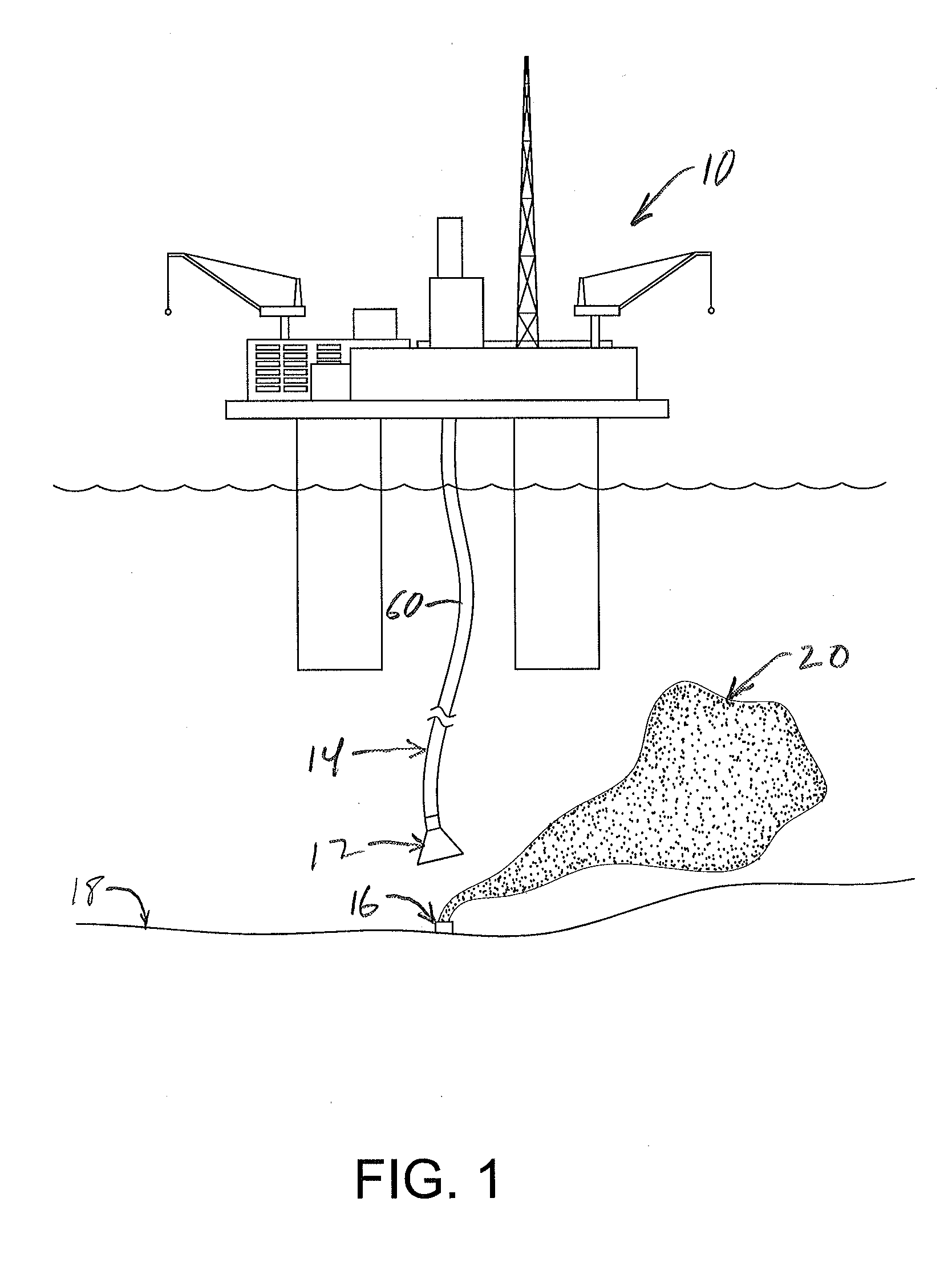
[0030]Referring to the drawings, wherein like or similar references indicate like or similar elements throughout the several views, there is shown in FIG. 1 an offshore oil rig from which an apparatus 12 according the present invention is suspended by a hose and cable arrangement 14. As seen in that figure, apparatus 12 is in the process of being deployed to control a gushing, uncontrolled undersea oil well, the head 16 of which is located at seafloor 18 and from which there is seen a rising plume of crude oil and gas 20.

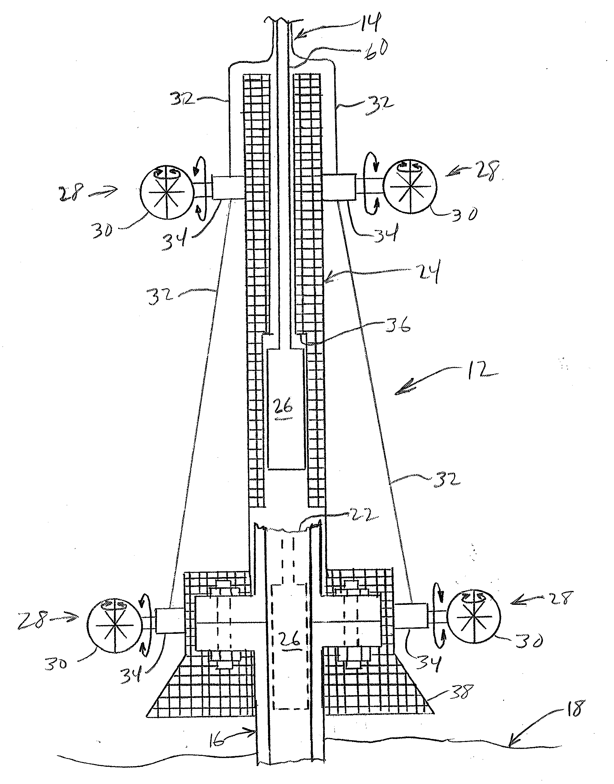
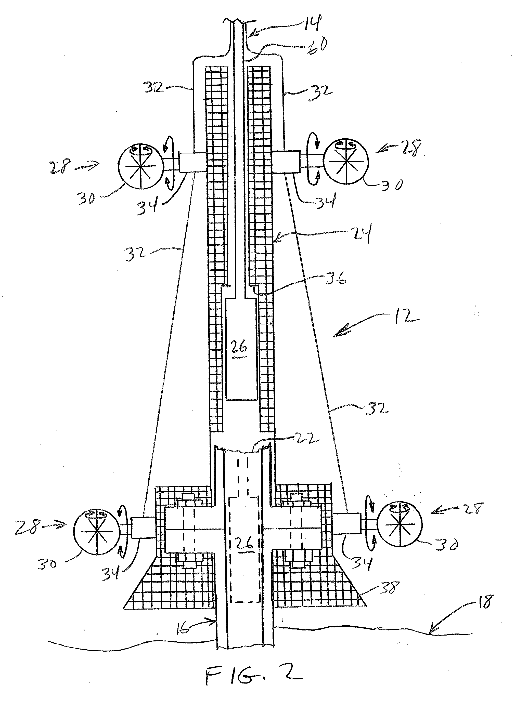
[0031]FIG. 2 illustrates on an enlarged scale apparatus 12, hose and cable arrangement 14 and oil wellhead 16. As seen in that figure, wellhead 16 is shown as having a severed top end 22 such as might occur following a catastrophic failure or blowout of the well. Apparatus 12 includes a housing 24 and a combined plug and valve device 26, which is schematically depicted in FIG. 2. Housing 24 is operable to protect and transport device 26 from a point of deployment at...


PUM


Abstract

A system including a combined plug and valve device that may be precisely delivered to and inserted into an uncontrolled undersea oil well. Once positioned in the well, the device is operated in graduated fashion to anchor the plug to the well and gradually stanch the flow of oil from the well.

Description

CROSS REFERENCE TO RELATED APPLICATION[0001]This application claims the benefit of U.S. Provisional Application No. 61 / 502,016, filed Jun. 28, 2011, the disclosure of which is incorporated herein in its entirety by reference thereto.FIELD OF THE INVENTION[0002]The present invention relates in general to oil well control systems and, in particular, to systems for managing the flow of crude oil and natural gas discharge from an uncontrolled undersea well.BACKGROUND OF THE INVENTION[0003]The 2010 crude oil spill in the Gulf of Mexico was a human and environmental disaster of epic proportions. It was the largest oil spill in history. From its beginning on Apr. 20, 2010 with the deadly explosion of the Deepwater Horizon oil drilling rig to Jul. 15, 2010 when the gushing well was effectively capped, the spill resulted in an estimated release of nearly 5 million barrels of crude oil that caused extensive damage to marine and wildlife habitats as well as the Gulf's fishing and tourism indus...

Claims


Application Information

Patent Timeline
IPC IPC(8): E21B43/01
CPCE21B43/0122E21B41/04
Inventor LINDERMAN, CHARLES EARLDYER, KARL BACHMANBANDURA, RYAN ALEXANDERRAMANUJACHARY, KANDALAM VENKATACONSTANS, ERIC WILLIAM
Owner ROWAN UNIVERSITY
Learn More