Wind Turbine

a wind turbine and wind power technology, applied in the direction of wind power motors with perpendicular air flow, non-positive displacement fluid engines, liquid fuel engine components, etc., can solve the problems of high manufacturing and maintenance costs, wind power can be damaged or destroyed, and the design of wind power cannot meet the needs of residential buildings or high rise buildings, so as to setup and overall maintenance requirements, and reduce the complexity of manufacturing, transportation, the effect of enhancing the efficiency of electrical energy

Active Publication Date: 2013-01-03
SP POWER FARM GRP
View PDF1 Cites 34 Cited by
  • Summary
  • Abstract
  • Description
  • Claims
  • Application Information

AI Technical Summary

Benefits of technology

[0013]Another objective of the present invention is that the wind turbine allows multiple energy output.
[0014]Another objective of the present invention is that the wind turbine is designed to reduce the complexity of manufacturing, transportation, setup, and overall maintenance requirements.
[0015]Another objective of the present invention is that the wind turbine, wherein the turbine rotor is the only major moving component of the wind turbine, so that the traditional gearbox, yaw, motors, and pitch control system will be eliminated to reduce the maintenance of the wind turbine. Thus, no complicated casting or component used or required.
[0016]Another objective of the present invention is that the wind turbine provides a mono-rail system with multiple bearing supports to guide and support the rotation of the turbine rotor via multiple stands around the circumference of the turbine rotor 204. Therefore, the mono-rail system can remove the loads generated from the traditional center bearings to the circumference of the turbine rotor.
[0017]Another objective of the present invention is that the turbine wheel system is stackable that one turbine wheel system is stacked on top of another turbine wheel system to enhance the efficiency of electrical energy production and to reduce the land usage to build the wind turbine.
[0018]Another objective of the present invention is that the turbine wheel system is housed in a housing to protect wildlife and reduce noise. The housing is further able to incorporate with other forms of renewable energy system such as mounting solar panels at the roof of the housing and / or providing space inside the housing for hydrogen generation (HOGEN) storage system for any excess energy production storage.

Problems solved by technology

The structure of the conventional wind turbine is complicated and required high manufacturing and maintaining cost.
Since the wind turbine must be set up at a high wind-load area, the wind turbine can be damaged or destroyed by heavy storm or lightning.
Therefore, the design of wind turbine does not fit for residential building or high rise building since the high rise building does not provide enough space to set up the wind turbine.
There have been instances in the past, when the rotating blades of the wind turbines have proved fatal for birds that happened to hit it.
The design of wind turbine may destroy the beauty of the land.

Method used


Image

  • Wind Turbine
  • Wind Turbine
  • Wind Turbine

Examples


Embodiment Construction

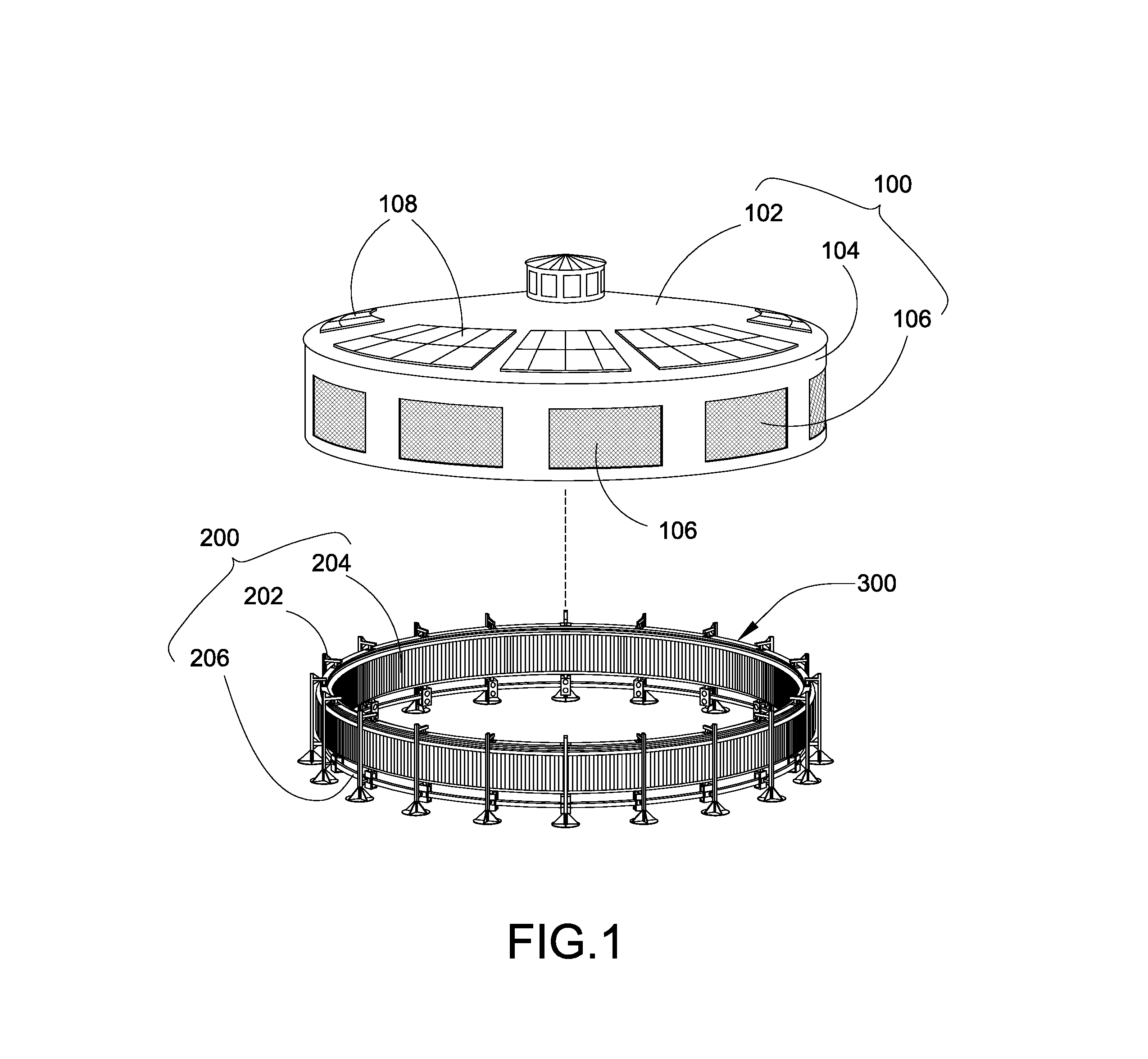
[0040]In accordance with a preferred embodiment of the present invention, the present invention provides a wind turbine which is comprised of a turbine housing 100, a turbine wheel system 200, and a wind power converting system 300.

[0041]FIG. 1 depicts the turbine housing 100 which is comprised of a top roof 102 and a circumferential wall 104 forming an interior, wherein a plurality of airflow screens 106 are formed at the circumferential wall 104 for enabling airflow flowing in and out the interior of the turbine housing 100 through the airflow screens 106. The top roof 102 has an air vent for air circulation.

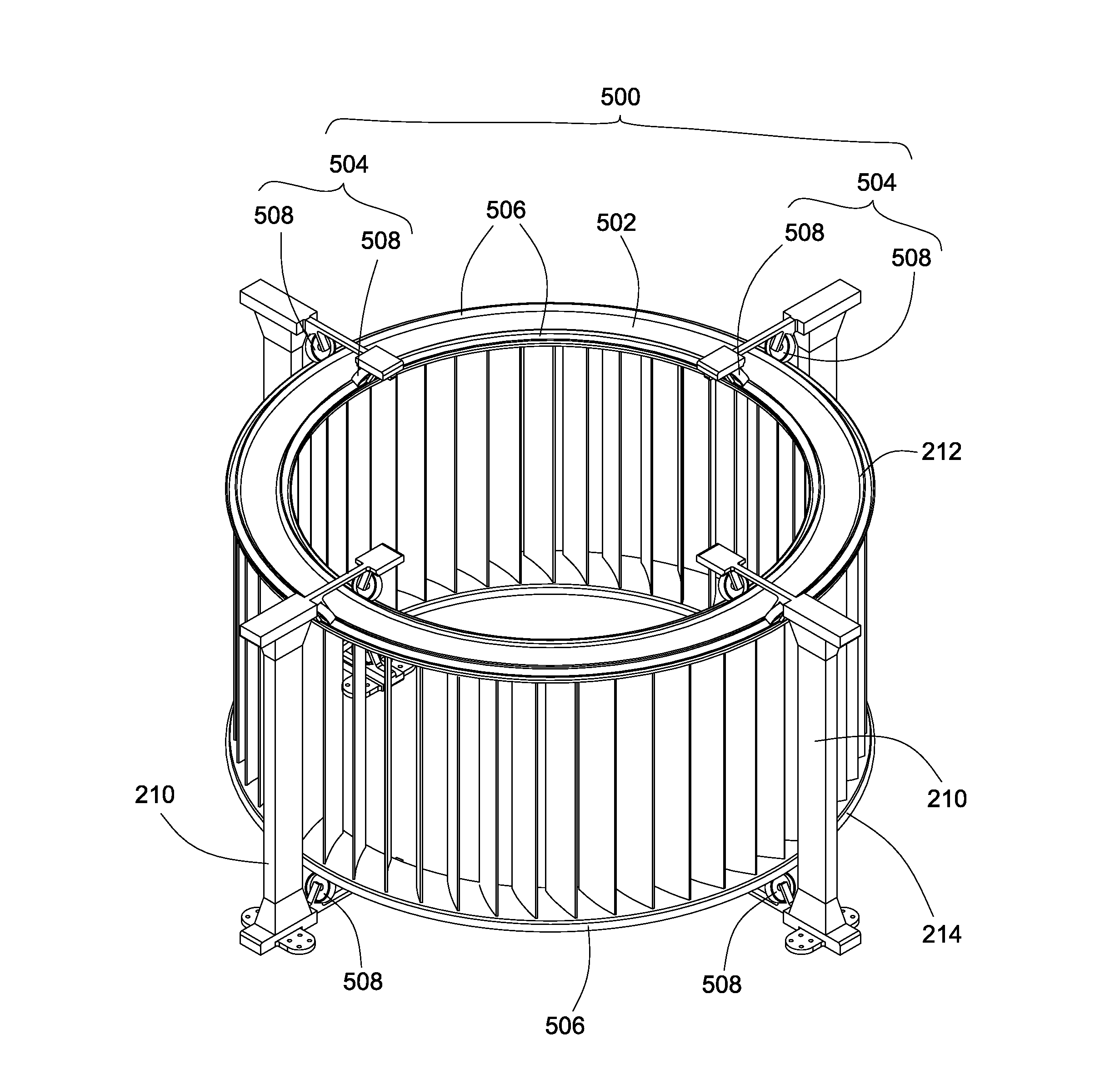
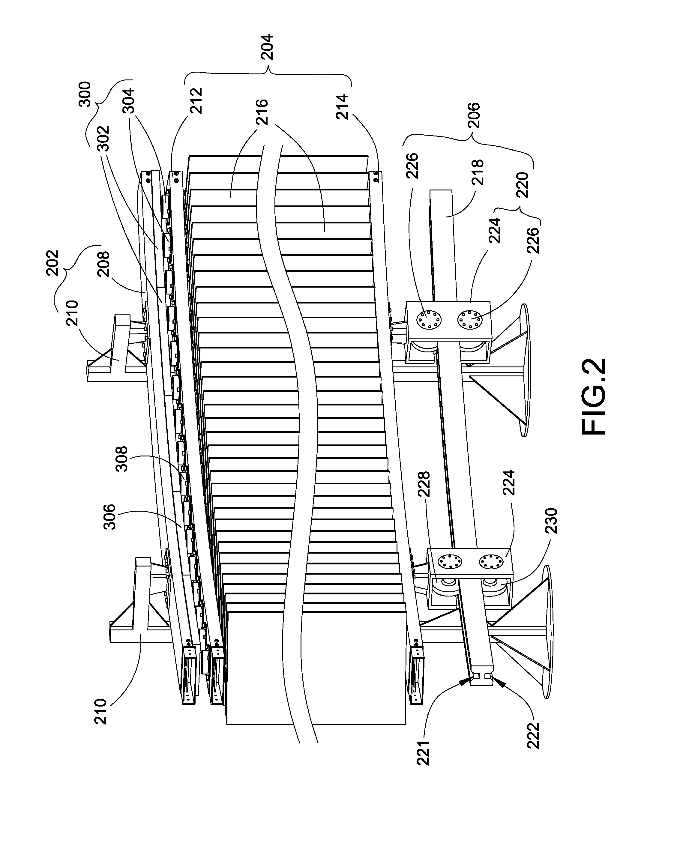
[0042]FIGS. 1 and 2 depict the turbine wheel system 200 being received in the turbine housing 100. The turbine wheel system 200 is comprised of a supporting frame 202, a turbine rotor 204 supported by the supporting frame 202, and a rail frame 206 coupled to the supporting frame 202 to guide a rotational movement of the turbine rotor 204.

[0043]The turbine rotor 204 is rotated ...


PUM


Abstract

A wind turbine includes a turbine housing, a turbine wheel system housed in the turbine housing, and a wind power converting system for converting kinetic energy generated by the turbine wheel system into electrical energy. The turbine wheel system includes a turbine rotor being driven to rotate circumferentially around an interior of the turbine housing, and a rail frame guiding a rotational movement of a turbine rotor. The wind turbine not only allows airflow to move across and through the turbine wheel system but also allows airflow to be directed and exhausted to maximize and control energy generation. The wind turbine is able to efficiently convert wind power to electrical power via a turbine wheel system which allows for the load generated to be distributed across the circumference of the turbine wheel system instead of localized in the center as the traditional wind turbine.

Description

BACKGROUND[0001]1. Field of the Invention[0002]The present invention relates to a wind turbine. More particularly, the present invention relates to a wind turbine which not only allows airflow to move across and through the wind turbine but also allows airflow to be directed and exhausted to maximize and control energy generation.[0003]2. Discussion of the Related Art[0004]The potential for an energy crisis has never been, higher. Alternative energy, such as solar energy or wind energy, has got the potential to play an extremely important role in the foreseeable future with the planet's energy production. Alternative energy sources are renewable and are thought to be free energy sources. Wind power is now the world's fastest growing energy source and has become one of the most rapidly expanding industries since wind power is considered as safe and clean energy, and is one of the cheapest forms of energy available today.[0005]Generally speaking, there are two basic types of wind turb...

Claims


Application Information

Patent Timeline
Patent Type & Authority Applications(United States)
IPC IPC(8): F03D9/00F03D11/02
CPCF03D3/065Y02E10/74F05B2220/7068F03D80/70F03D15/00F03D13/20F03D9/25Y02E10/728F03D9/007F03D15/10H02S10/12Y02E10/50F03D3/062F03D3/005
Inventor ARMSTRONG, THOMAS B.
Owner SP POWER FARM GRP
Why Eureka
Try Eureka