Optical coherence tomography apparatus and method
a coherence tomography and optical coherence technology, applied in the field of optical coherence tomography apparatus and method, can solve the problems of reducing sensor sensitivity, difficulty in increasing vertical resolution, and wavelength band also having a limit on a long wavelength sid
- Summary
- Abstract
- Description
- Claims
- Application Information
AI Technical Summary
Benefits of technology
Problems solved by technology
Method used
Image
Examples
first embodiment
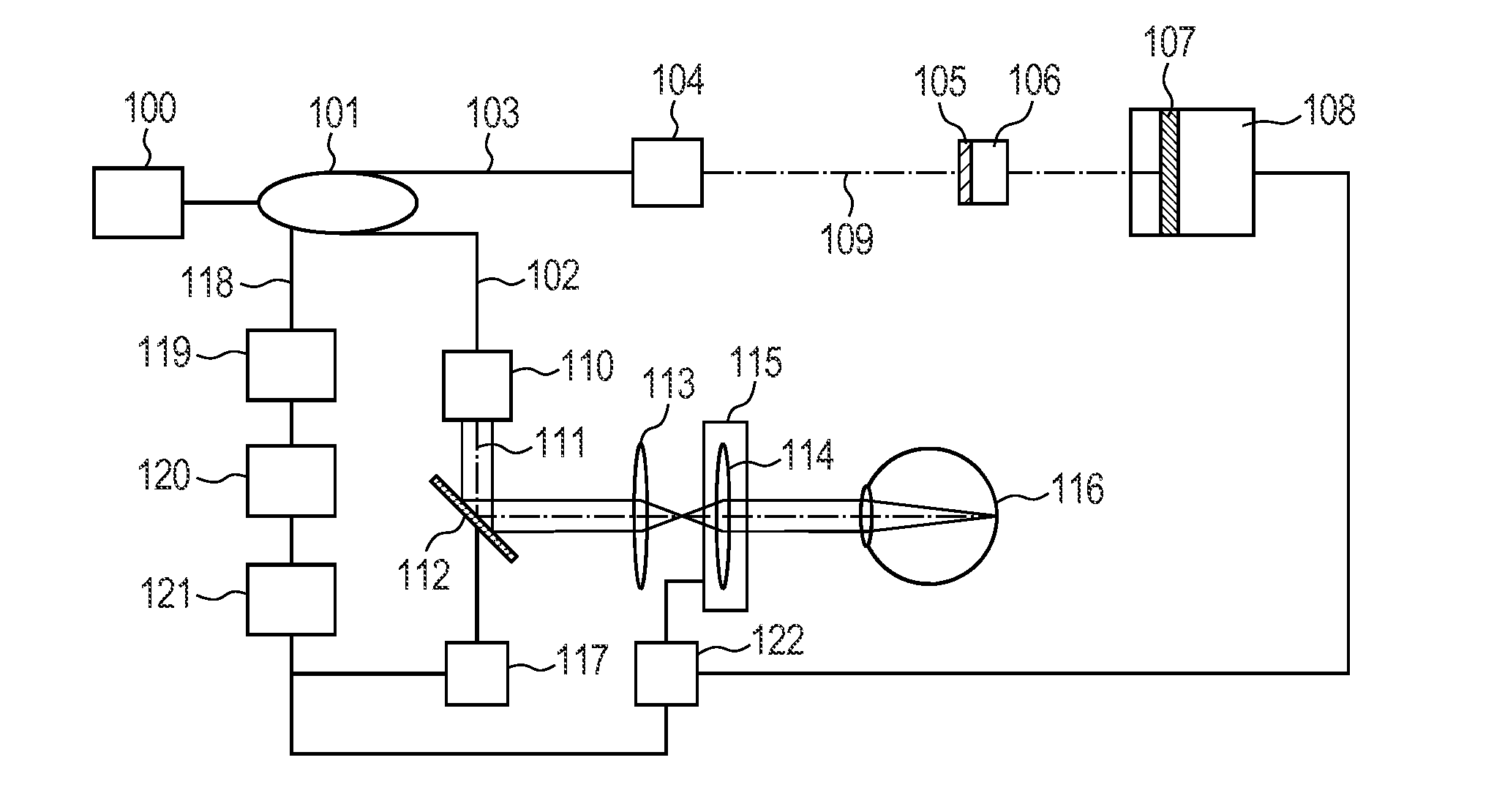
[0034]With reference to FIG. 1, an optical coherence tomography apparatus according to the present invention will be described.
[0035]FIG. 1 illustrates the optical coherence tomography apparatus as a specific example for carrying out the present invention.
[0036]In FIG. 1, a light source 100 is an SLD (Super Luminescent Diode) in the present embodiment, but may be any low-coherence light source. The specific examples include an ASE (Amplified Spontaneous Emission) light source, an ultrashort pulse light source such as a titanium sapphire laser and an SC (Super Continuum) light source, and an SS (Swept Source) light source. The wavelength band is near 850 nm, but it is desirable that the wavelength band be selected according to the purpose because if a deeper portion of the object to be inspected needs to be measured at the expense of the vertical resolution, a light source having a longer wavelength band is used.
[0037]A fiber coupler 101 splits broadband light emitted from the light ...
second embodiment
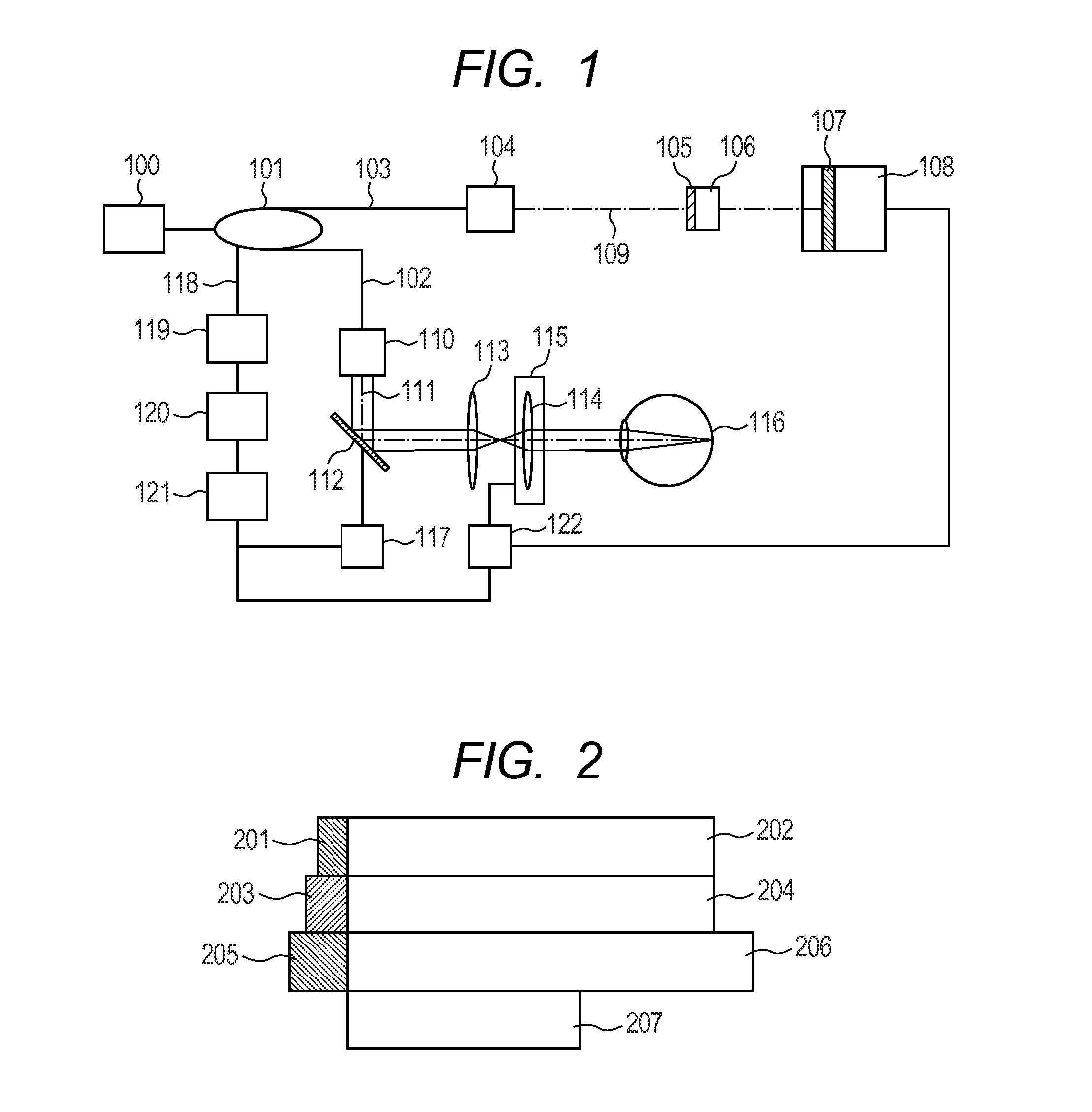
[0058]In the present embodiment, a plurality of composite dispersion compensation members including materials 1 and 2 satisfying expression (4) is arranged each having a different thickness as illustrated in FIG. 2.
[0059]The present embodiment can provide the dispersion compensation members each suitably compensating for nearsightedness, normal sightedness, or farsightedness. FIG. 2 illustrates dispersion compensation members 201 and 202 for use in measuring an object to be inspected for farsightedness; dispersion compensation members 203 and 204 for normal sightedness with normal axial length; and dispersion compensation members 205 and 206 for nearsightedness. More specifically, the present embodiment uses the conditions listed in the following Table 1.
TABLE 1ThicknessThicknessPolycarbonate(mm)BK7(mm)2011.7202232032204232052.220623.7
[0060]A dispersion compensation member 207 is provided for calibration when a schematic eye or a mirror is placed as the object to be inspected. The a...
PUM
 Abstract
Description
Claims
Application Information
 - R&D
- Intellectual Property
- Life Sciences
- Materials
- Tech Scout
- Unparalleled Data Quality
- Higher Quality Content
- 60% Fewer Hallucinations
Browse by: Latest US Patents, China's latest patents, Technical Efficacy Thesaurus, Application Domain, Technology Topic, Popular Technical Reports.
© 2025 PatSnap. All rights reserved.Legal|Privacy policy|Modern Slavery Act Transparency Statement|Sitemap|About US| Contact US: help@patsnap.com


