Hybrid electric drive unit, hybrid drive system and control method thereof

Active Publication Date: 2013-01-03
SAIC MOTOR
View PDF9 Cites 21 Cited by
  • Summary
  • Abstract
  • Description
  • Claims
  • Application Information

AI Technical Summary

Benefits of technology

[0012]By means of a simple and effective design, the hybrid drive system provided by the present invention can realize a series/parallel power output of hybrid vehicle by taking advantage of selective power outputs of the engine and two motors properly, and can switch among different operating modes based on different road conditions and battery volumes, so as to achieve energy saving and environment protection for hybrid vehicle and meet demands on system performances as required under different road conditions. At least on the basis of current existing technology, the present invention provides a hybrid drive system which consists of a first shaft, a first clutch, a second clutch, a synchronizer, a first stage decelerating device, a second stage decelerating device, a first gear drive gear, a second gear drive gear, a main traction motor, a integrated starter-generator, an engine and other components, etc., so that a proper connection of individual power sources is realized

Problems solved by technology

However, this method is complex in power transmission path, and there is a phenomenon that power transmission loss is caused unnecessarily by converting mechanical energy into electric energy and then converting the converted electric energy into mechanical energy to output.
Therefore, if this method is applied for a plug-in hybrid vehicle, it will lead to the loss of efficiency of the hybrid mode of the hybrid drive vehicle.
In addition, since all output power is output by planetary gear carrier of the planetary line, the requirements for the costs on material and the manufacturing of the planet gear carrier are very high.
However, under the condition that a vehicle is in pure electric drive, it is very difficult to meet all design requirements in terms

Method used


Image

  • Hybrid electric drive unit, hybrid drive system and control method thereof
  • Hybrid electric drive unit, hybrid drive system and control method thereof
  • Hybrid electric drive unit, hybrid drive system and control method thereof

Examples


Embodiment Construction

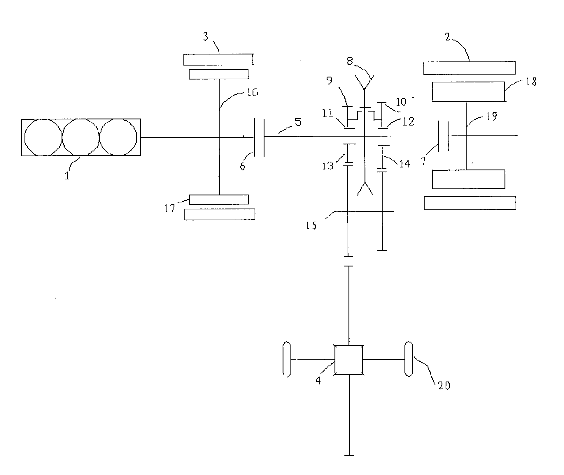
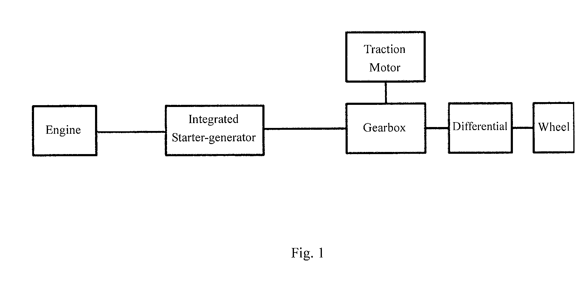
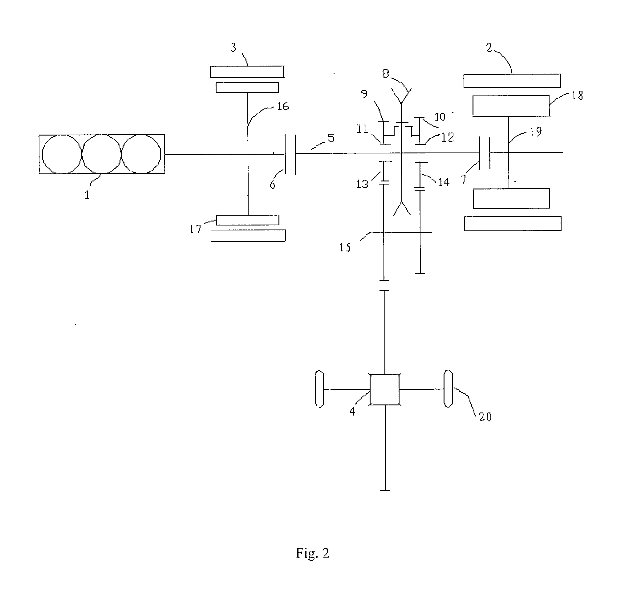
[0018]FIG. 1 illustrates a principle diagram showing connection relationships among components in a drive system of hybrid vehicle according to a specific embodiment of the present invention. It illustrates connection relationships among the engine 1, the wheel 20, the electric drive unit including the first motor 2 and the second motor 3, differential 4 and the other components of a hybrid vehicle applied with the hybrid drive system of the present invention, wherein the engine 1 and the electric drive unit comprise the hybrid drive system of the present invention. Preferably, the first motor 2 is a main traction motor of the hybrid vehicle of the present invention, and the second motor 3 is an integrated starter-generator. Specifically, the engine 1 is connected to the electric drive unit, through which hybrid power is transmitted to the wheel 20 via the differential 4. The specific connection manner and operating modes will be described in detail in the following specific embodim...


PUM


Abstract

A series/parallel hybrid electric drive unit for vehicle comprises an engine (1), a main traction motor (2), an integrated starter-generator (3), a differential (4), a first shaft (main haft) (5), a first stage decelerating device (9), a second stage decelerating device (10), a first clutch (6), a second clutch (7) and a synchronizer (8). The synchronizer (8) is slidably arranged on the first shaft (5) which is connected to the first stage decelerating device (9) or the second stage decelerating device (10) by the synchronizer (8), respectively. The hybrid electric drive unit of the invention has a compactly-arranged internal structure and an efficient and appropriate internal connection, and a switch between connection and disconnection of respective hybrid power sources and wheels and a shifting among operating modes and gear positions of the hybrid drive system can be realized.

Description

FIELD OF THE INVENTION[0001]The present invention relates to a hybrid vehicle, in particular a plug-in hybrid vehicle, and more specifically to a hybrid drive unit for vehicle with clutches and a synchronizer coupled in power transmission relationship for shifting, and a corresponding hybrid drive system as well as a driving and shifting method preferably corresponding to the hybrid drive unit and system.BACKGROUND OF THE INVENTION[0002]Since energy saving and environmental protection currently become the main focus in the development of automobile industry, hybrid vehicles have been turned into a main core technology and pursued by many automobile manufactures globally. Wherein, the solution of plug-in hybrid vehicles, except pure electric drive vehicles, is one of the most fuel saving solutions, and it has being advocated by many major automobile manufacturers. A plug-in hybrid vehicle primarily consists of a relative lower displacement engine and one or two motors. Under normal c...

Claims


Application Information

Patent Timeline
IPC IPC(8): B60W10/12B60W10/18B60W10/02F16H37/08B60W10/10B60W10/11B60W30/19
CPCB60K6/442Y10T477/24Y02T10/6286B60K6/54B60W10/02B60W10/06B60W10/08B60W10/11B60W30/19B60K2006/541Y02T10/6243Y02T10/6269B60K6/387B60K6/547Y10T477/26Y10T74/19223Y10T477/23Y02T10/6234B60L15/2054Y02T10/72B60L50/61B60L50/16Y02T10/62Y02T10/64Y02T10/7072Y02T10/70
Inventor CHEN, HONGCHEN, ZHIXINGAO, WEIMINZHU, JUNLUO, SIDONGGE, HAILONG
Owner SAIC MOTOR
Why Eureka
Try Eureka