Vibration insulator for fuel injection valve, and support structure for fuel injection valve
a technology of vibration insulation and fuel injection valve, which is applied in the direction of noise reduction fuel injection, mechanical equipment, machines/engines, etc., can solve the problems of thermal deformation, various vibrations that accompany the operation of the internal combustion engine, and changes in relative positions of assembly, etc., to improve the reliability and stability of the support structure of the fuel injection valv
- Summary
- Abstract
- Description
- Claims
- Application Information
AI Technical Summary
Benefits of technology
Problems solved by technology
Method used
Image
Examples
first embodiment
[0050]A vibration insulator according to a first embodiment of the present invention will be described with reference to the drawings.
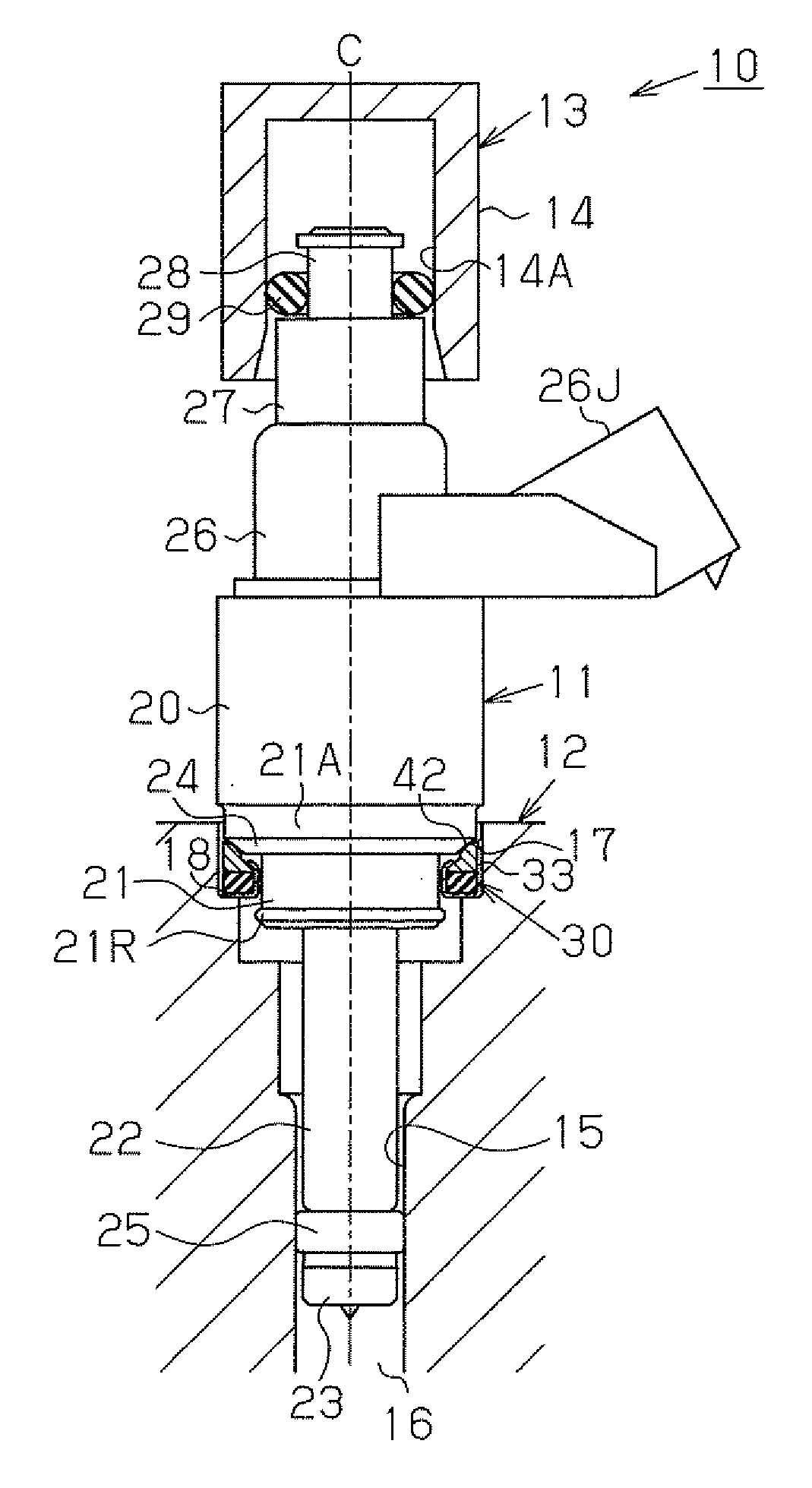
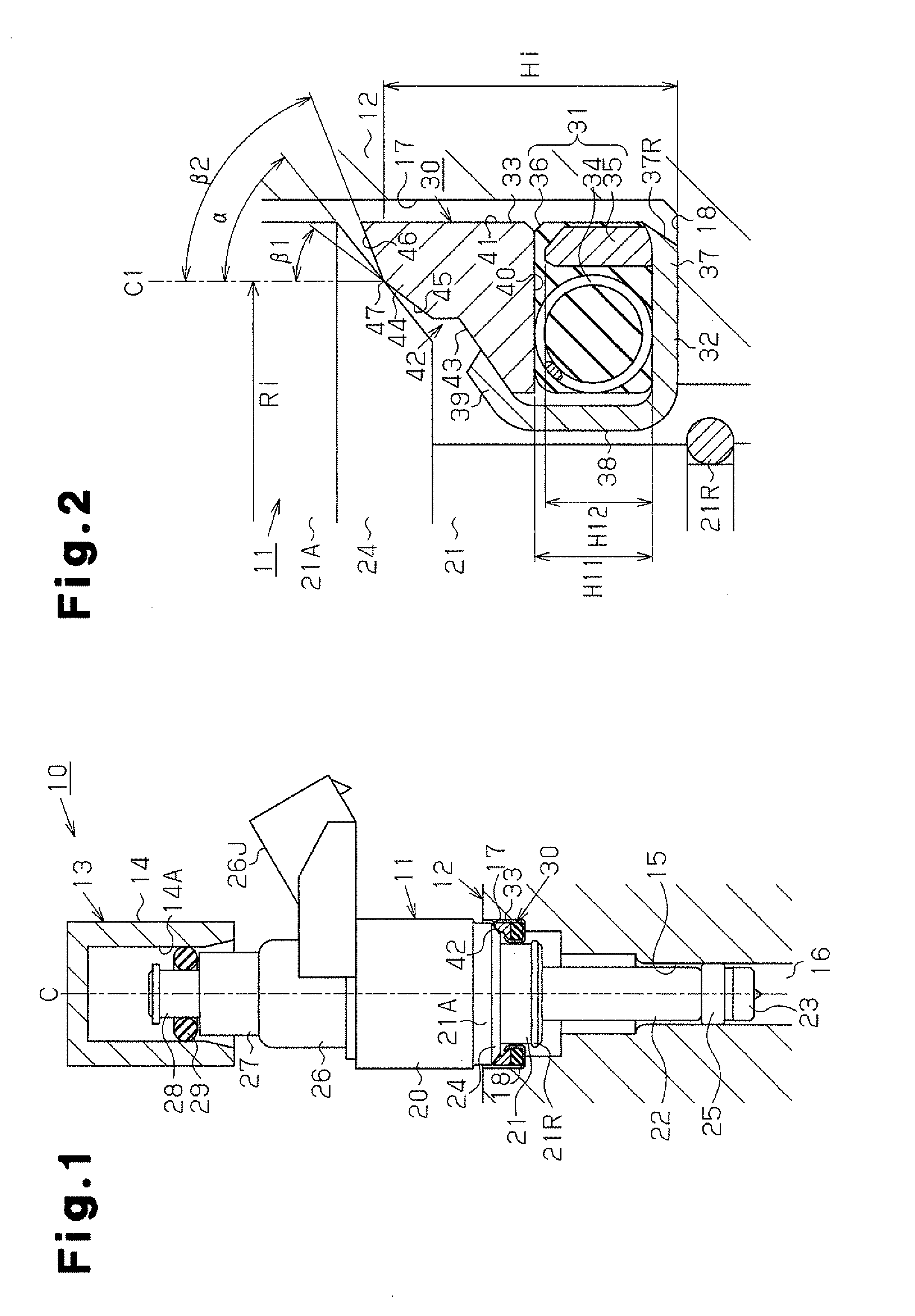
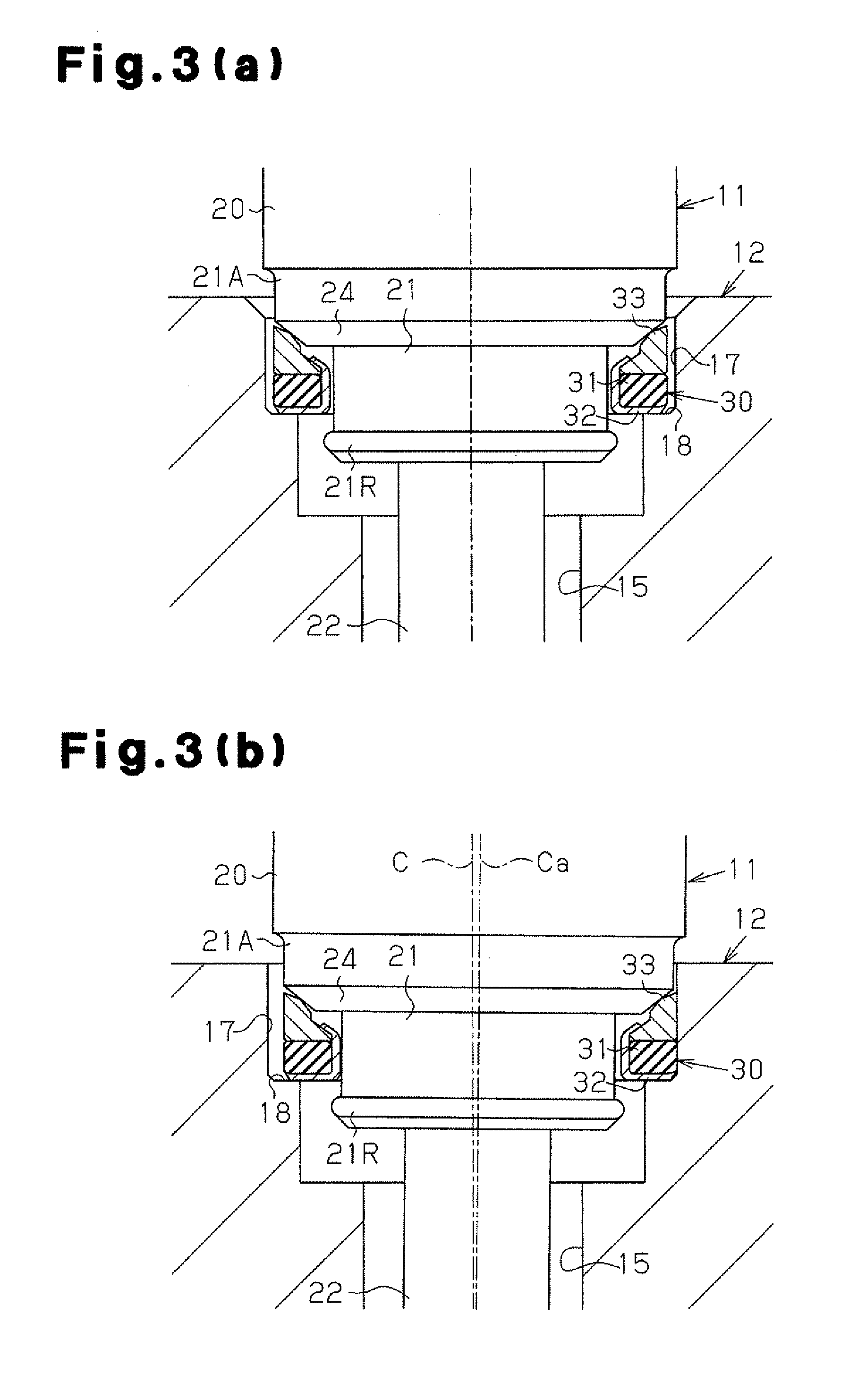
[0051]FIG. 1 is a diagram schematically showing the structure of a fuel injection system 10 to which a vibration insulator 30 according to this embodiment is applied. FIG. 2 is a diagram showing the structure of an end face of the vibration insulator 30 in an end view. FIGS. 3(a) and 3(b) are diagrams for illustrating the states of compensating for movement of the vibration insulator 30. FIG. 3(a) shows the fuel injection valve 11 in the state where the axis C thereof is not inclined.
[0052]As shown in FIG. 1, the fuel injection system 10 is provided with a fuel injection valve 11. A part of the fuel injection valve 11 in the distal end portion is supported by the insertion hole 15 of the cylinder head 12, and another part of the fuel injection valve 11 in the proximal end portion is supported by the fuel injection valve cup 14 of the delivery pipe 13....
second embodiment
[0100]FIG. 4 is an end view showing the structure of a vibration insulator 30 according to a second embodiment of the present invention. Since this embodiment differs from the first embodiment in structure of the tolerance ring of the vibration insulator 30 but the other structures are the same, differences from the first embodiment are mainly described, and description of members similar to those of the first embodiment is omitted by assigning the same reference signs thereto, for illustrative purposes.
[0101]As shown in FIG. 4, the vibration insulator 30 is formed by sequentially stacking a vibration damping member 31 and a tolerance ring 33A on a plate bottom section 37 of a plate 32.
[0102]The tolerance ring 33A, as in the case of the first embodiment, supports the fuel injection valve 11 by abutting the tapered surface 24 of the fuel injection valve 11 and is formed of metal such as stainless steel. Also, the tolerance ring 33A, as in the case of the first embodiment, includes th...
third embodiment
[0109]FIG. 5 is an end view showing the structure of a vibration insulator 30 according to a third embodiment of the present invention. Since this embodiment differs from the first embodiment in structure of the vibration damping member of the vibration insulator 30 but the other structures are the same, differences from the first embodiment are mainly described, and description of members similar to those of the first embodiment is omitted by assigning the same reference signs thereto, for illustrative purposes.
[0110]As shown in FIG. 5, the vibration insulator 30 is formed by sequentially stacking the vibration damping member 31B and the tolerance ring 33 on the plate bottom section 37 of the plate 32. The vibration damping member 31B is a member for absorbing and damping vibration of the fuel injection valve 11 and includes an elastic member 36 such as rubber, a coil spring 34 annularly embedded in the elastic member 36 and a sleeve 35B located from the coil spring 34 toward the i...
PUM
 Abstract
Description
Claims
Application Information
 - R&D
- Intellectual Property
- Life Sciences
- Materials
- Tech Scout
- Unparalleled Data Quality
- Higher Quality Content
- 60% Fewer Hallucinations
Browse by: Latest US Patents, China's latest patents, Technical Efficacy Thesaurus, Application Domain, Technology Topic, Popular Technical Reports.
© 2025 PatSnap. All rights reserved.Legal|Privacy policy|Modern Slavery Act Transparency Statement|Sitemap|About US| Contact US: help@patsnap.com


