
Frequency-controlled exhaust bellows assembly

Inactive Publication Date: 2013-01-17
TRU FLEX
View PDF11 Cites 19 Cited by
  • Summary
  • Abstract
  • Description
  • Claims
  • Application Information

AI Technical Summary

Benefits of technology

The patent describes a cover for a coupler that limits the amount of growth in length and enables compression and angular flexibility. The cover is designed to provide resistance to noise and heat transmission while retaining as much heat in the exhaust gas as possible. The cover is applied to the coupler's conduit portion and includes insulation material to suppress noise and heat transmission. The technical effects of the cover include reducing energy consumption and noise levels while maintaining performance and flexibility of the coupler.

Problems solved by technology

Vibrations from one or more components connected to the exhaust system, for example, engine vibrations and vibrations induced through movement of the vehicle, can cause stress on, and premature failure of, the components within the exhaust system.
In such cases, the components within the exhaust system, including the flexible connection members, can be fatigued to the point of cracking thereby rendering the components ineffective.
Torsional forces caused by differential rotation of the exhaust system components with respect to one another can inflict significant damage on such components.
Such dynamic torsional forces, which can be generated within the vehicle or through the flexing of its frame as it maneuvers uneven terrain, can lead to premature metal fatigue, cracking and other failure of the exhaust system components.

Method used


Image

  • Frequency-controlled exhaust bellows assembly
  • Frequency-controlled exhaust bellows assembly
  • Frequency-controlled exhaust bellows assembly

Examples


Embodiment Construction

[0022]The invention will now be described with reference to the drawing figures, in which like reference numerals refer to like parts throughout. For purposes of clarity in illustrating the characteristics of the present invention, proportional relationships of the elements have not necessarily been maintained in the drawing figures.

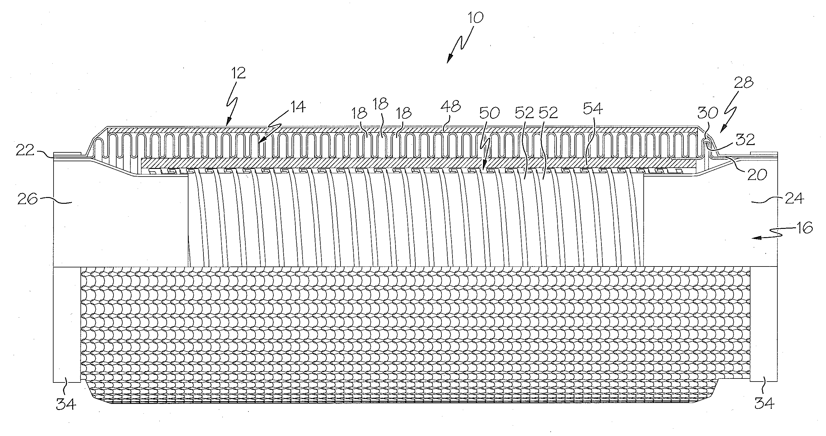
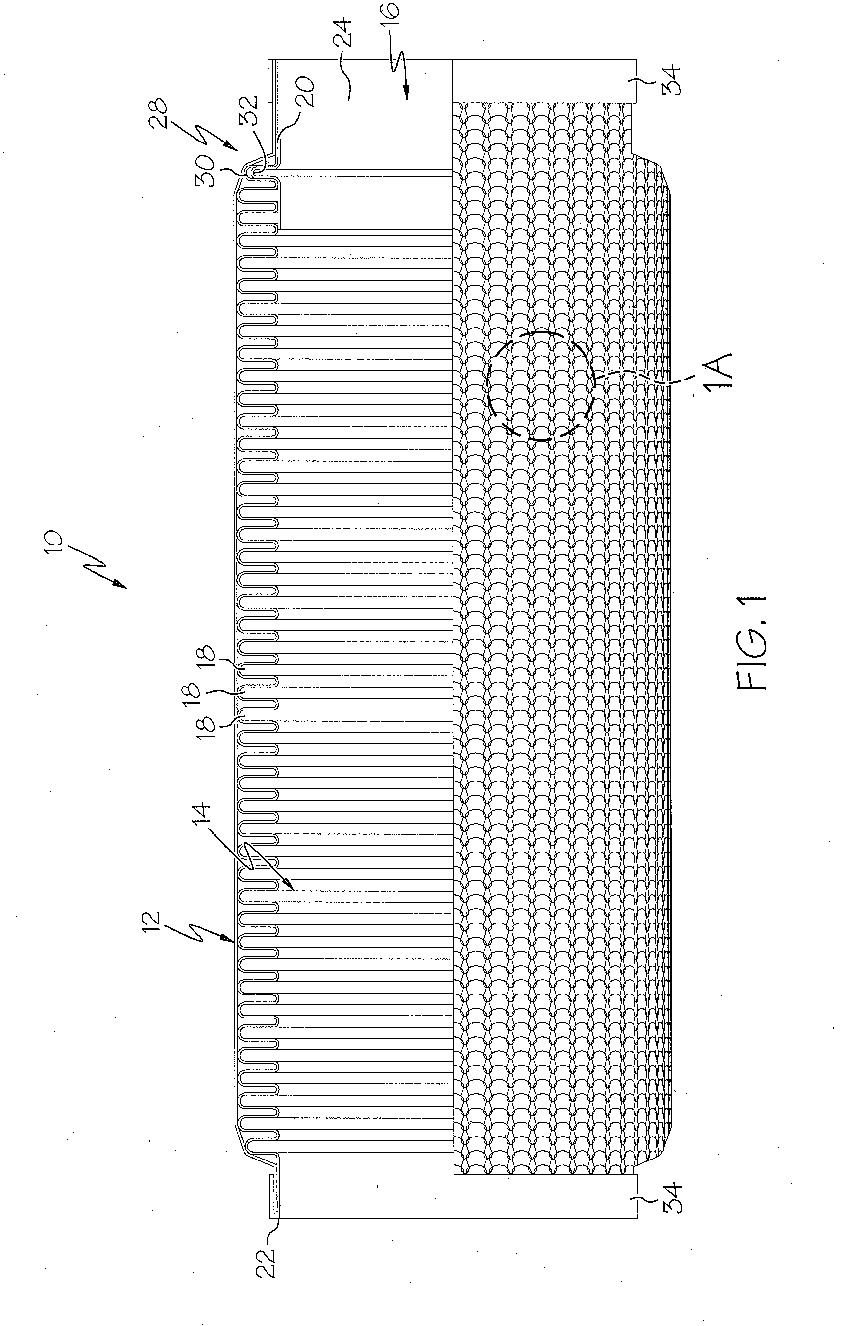
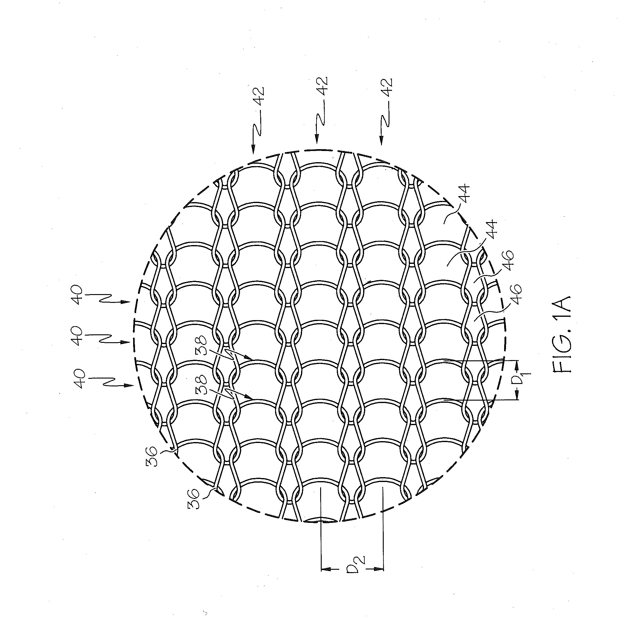
[0023]The present invention is directed generally toward a flexible exhaust connection member or coupler 10 that includes, among other components, a loosely knitted wire mesh cover 12. The coupler has a flexible internal conduit having a generally tubular shape and a passageway through which exhaust gasses can flow. As described in further detail below, the conduit may comprise a bellows member 14 and / or an interlock member 50. In one embodiment, the cover 12 is constructed of a series of knitted stockinette stitches formed in a continuous round-and-round manner in a seamless tubular configuration.

[0024]As illustrated in FIG. 1, the coupler 10 includes a...


PUM


Abstract

An exhaust connection coupler is provided having a flexible conduit portion, a cover made of a generally porous and flexible knitted metallic wire mesh material surrounding the conduit portion and a retainer for combining end parts of the conduit portion and cover. The cover may be constructed of a series of stockinette stitches formed in a continuous round-and-round manner in a seamless tubular configuration. The cover can be selected from a group of covers designed to be applied to the coupler, the particular cover being chosen for its weight or stiffness so as to selectively control the natural frequency of the coupler. Additionally, the loosely knitted configuration of the cover is designed to provide resistance limiting longitudinal growth of the coupler while enabling compression and angular flexibility. Further, the coupler may include one or more spacers for providing separation between the cover and the conduit portion.

Description

CROSS-REFERENCE TO RELATED APPLICATIONS[0001]This application is a Non-Provisional application and claims priority to U.S. Provisional Patent Application Ser. No. 61 / 507,508 filed Jul. 13, 2011 to Clark Thomas and Scott R. Swank entitled “Frequency Controlled Exhaust Bellows Assembly,” currently pending, the entire disclosure of which is incorporated herein by reference. This application also claims priority to U.S. patent application Ser. No. 12 / 942,684, filed on Nov. 9, 2010 to Robert F. Stalcup II and Scott R. Swank entitled “Exhaust Connection Member with Preformed Braided Cover,” currently pending, the entire disclosure of which also is incorporated herein by reference. This application further claims priority to U.S. patent application Ser. No. 12 / 942,828 filed Nov. 9, 2010 to Robert F. Stalcup II and Scott R. Swank entitled “Compressible Exhaust Connection Member,” currently pending, the entire disclosure of which also is incorporated herein by reference.BACKGROUND OF THE INV...

Claims


Application Information

Patent Timeline
IPC IPC(8): F16L27/107F16L59/153F16L27/11
CPCF01N13/1816F16L59/21F16L27/1004F16L27/111F01N2310/14F16L51/027F01N2260/18F01N2260/20F16L51/026
Inventor THOMAS, CLARKSWANK, SCOTT R.
Owner TRU FLEX
Learn More