Electronic Device

a technology of electronic devices and fins, which is applied in the direction of electrical apparatus casings/cabinets/drawers, cooling/ventilation/heating modifications, instruments, etc., can solve the problems of affecting the cooling effect of the fan, the inability to adjust the temperature of the fan, etc., to achieve sufficient heat dissipation effect of the heat dissipation unit, the effect of simple structur

Active Publication Date: 2013-01-17
PANASONIC CORP
View PDF3 Cites 16 Cited by
  • Summary
  • Abstract
  • Description
  • Claims
  • Application Information

AI Technical Summary

Benefits of technology

[0016]In the electronic device having the features described above, the cleaning component for removing dust on the end surface of the fins to which heat emitted in the heat-emitting components transfers, moves with the cleaning component abutting against the end surface of the fins along the side nearer the fan, under its own weight. Thus, in a case where the spatial orientation of the electronic device is changed when, for example, the electronic device is carried, the cleaning component moves, so that the cleaning component can remove dust on the end surface of the fins while moving. Therefore, an electronic device can be obtained in which dust on an end surface of fins along the side nearer a fan can be removed with a simplified structure, and a stable heat-dissipating effect can be exerted over a long time period.
[0017]In another general aspect, in the electronic device having the features described above, while the heat-emitting component is operating and the fan is supplying cooling air, the cleaning component is accommodated in a retracted position, and the retracted position allows the cleaning component to be retracted from a region in which the cooling air supplied from the fan into the heat-dissipating component flows through the fins. Thus, when heat-emitting components are operating and heat is emitted therein, cooling air supplied from the fan to the heat-dissipating component is not blocked by the cleaning component, and a sufficient heat-dissipating effect of the heat-dissipating unit can be assuredly obtained.
[0018]In still another general aspect, the cleaning component includes: a cleaning component body abutting against the end surface of the fins on the fan side of the fins; and guide portions disposed on either of terminal ends of the cleaning component body, in which a surface area of each guide portion, which is orthogonal to the cleaning component lengthwise, is greater than a surface area of the cleaning component body, which is orthogonal to the cleaning component lengthwise. Further, guide grooves are formed for holding the guide portions within the casing, to regulate the cleaning component positionally. Thus, the cleaning component can be prevented from tilting relative to the heat-dissipating component, so that a smooth movement of the cleaning component can be assuredly obtained.
[0019]In still another general aspect, the cleaning component has a circular form in cross-section orthogonal to the cleaning component body lengthwise. Thus, movement of the cleaning component in a state where the cleaning component abuts against the end surface of the fins is facilitated, thereby assuredly removing adhered dust.

Problems solved by technology

However, when the intervals at which the fins disposed parallel to each other are formed are short, fine dust contained in the cooling air supplied from the fan is likely to adhere to, for example, the end surfaces of the fins along the side nearer the fan.
Once dust adheres to the fin end surfaces, dust is likely to accumulate rapidly.
Gaps among the fins tend to become filled with the accumulated dust, and the accumulated dust tends to cover the entire surface of the heat-dissipating component on the side where the cooling air supplied from the fan flows into the heat-dissipating component.
When dust accumulates, the fan cannot supply cooling air into the gaps among the fins, and consequently the cooling effect of the heat-dissipating unit deteriorates significantly.
Further, due to limitations on the extent to which the thermally deformable component is deformable, the mechanism for moving the workable component 102 is inevitably to be larger-scale.

Method used


Image

  • Electronic Device
  • Electronic Device
  • Electronic Device

Examples


embodiment

[0031]Hereinafter, an exemplary case in which an electronic device is a notebook computer will be described as an exemplary embodiment.

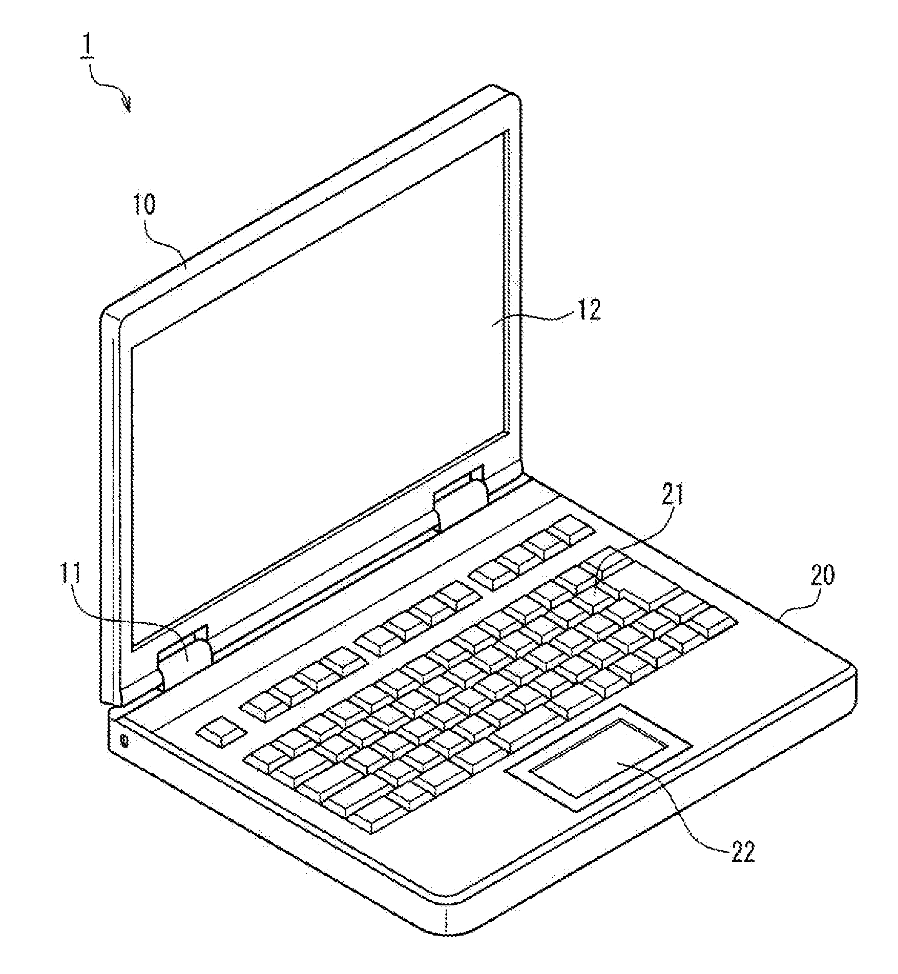
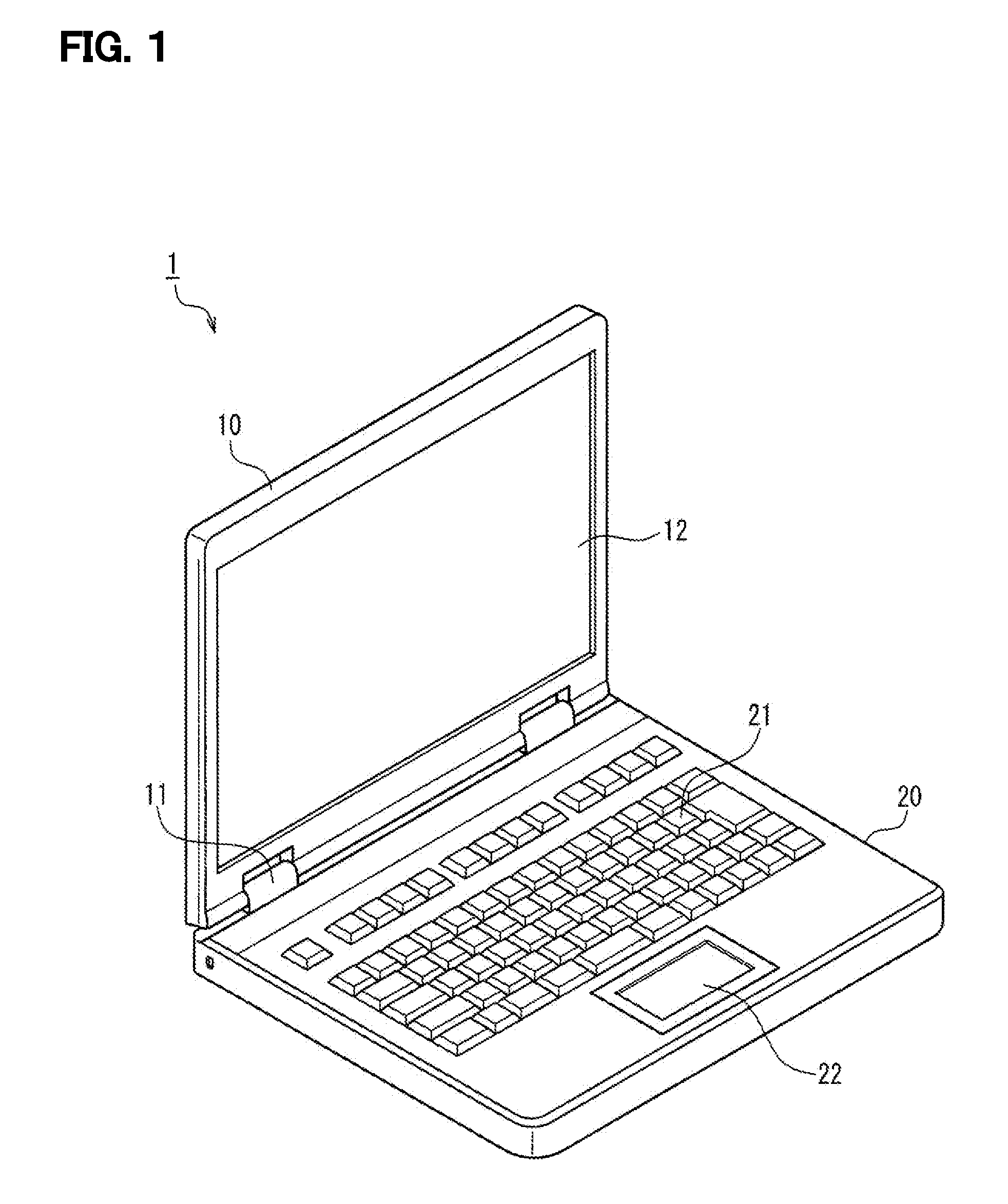
[0032]FIG. 1 illustrates a notebook computer 1 as an electronic device according to an exemplary embodiment.

[0033]The notebook computer 1 is structured such that a cover component 10 having a display device 12, such as a liquid crystal panel, disposed on an inner side surface thereof is mounted so as to be pivotable relative to a main unit 20 having input devices, such as a keyboard 21 and a pointing device 22, disposed on the surface thereof, by means of a hinge mechanism 11.

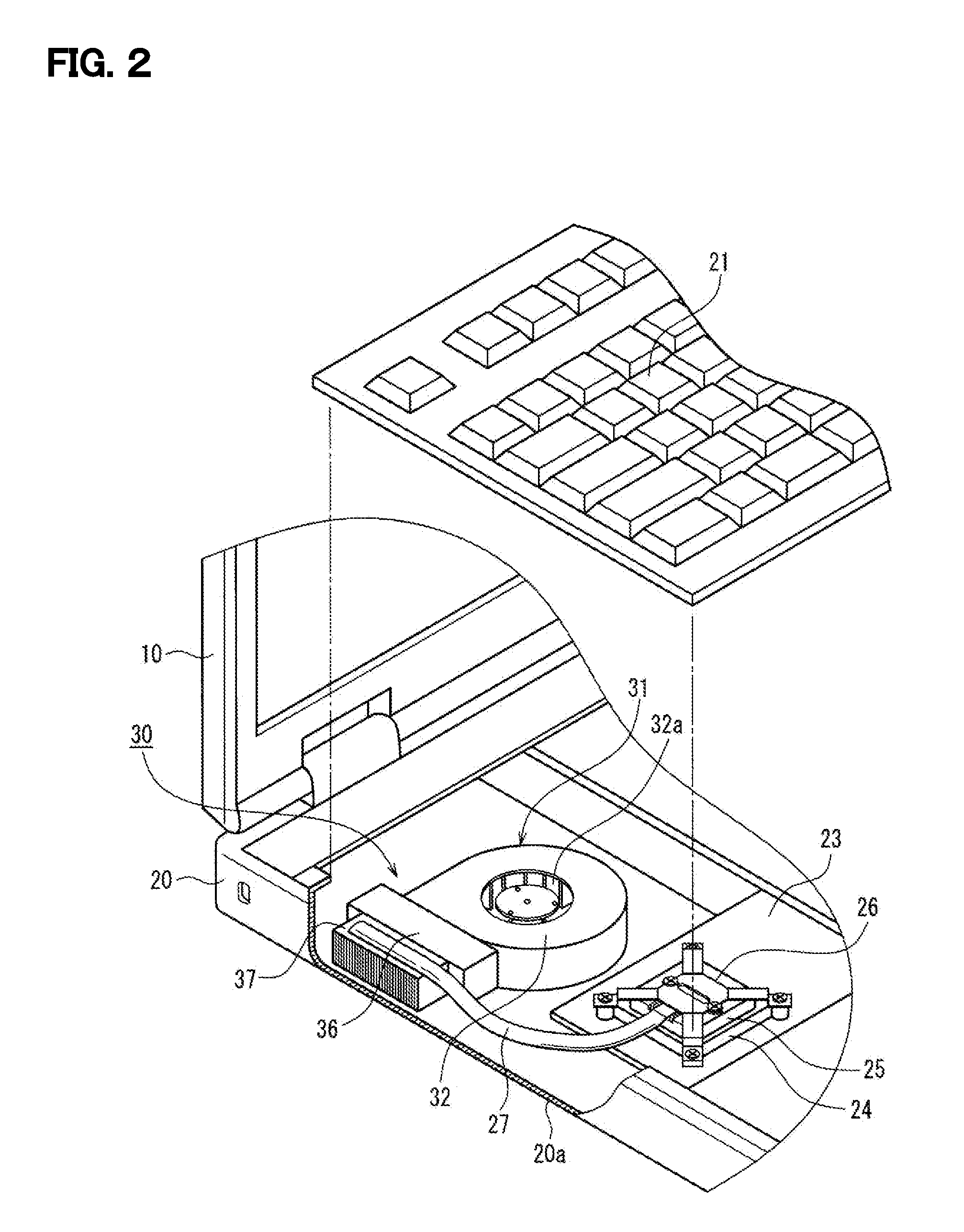
[0034]Inside the main unit 20, a secondary battery (not shown) for operating the notebook computer 1, a hard disk drive (HDD) (not shown) acting as a main storage device, and other electric components are disposed. The notebook computer 1 can include, for example, an antenna module for wireless LAN communication, a disk drive for blu-ray discs and DVD discs, a web camera device,...


PUM


Abstract

An electronic device includes: a casing in which electronic components including a heat-emitting component which emits heat during operation are accommodated; a heat-dissipating component including a plurality of fins to which heat emitted in the heat-emitting component transfers; a fan operable to supply cooling air to the heat-dissipating component; and a cleaning component movable on an end surface of the fins along the side nearer the fan with the cleaning component abutting against the end surface of the fins. In these features, dust on the end surface of the fins can be automatically removed by moving the cleaning component in the case of the spatial orientation of the electronic device being changed. Therefore, an effect of removing heat emitted in the heat-emitting components, by using cooling air supplied from the fan, can be continuously obtained.

Description

BACKGROUND [0001]1. Field[0002]The present disclosure relates to electronic devices—e.g., notebook computers and like electronic devices furnished with CPUs (central processing units)—having encased heat-emitting components that emit heat during operation, and in particular relates to the structure of heat-dissipating units that exteriorly release heat from heat-emitting components.[0003]2. Description of the Related Art[0004]Improving the performance of, for example, notebook computers—which are one instance of electronic devices—entails increase in the amount of heat emitted from the heat-emitting components such as the CPU. Further, a notebook computer is a portable electronic device, and to reduce its size and weight as a portable electronic device, the various electronic components are packed into the narrow inside of its casing. Therefore, the provision of heat-dissipating units that offer high performance by effectively releasing to the casing exterior the heat emitted from t...

Claims


Application Information

Patent Timeline
Patent Type & Authority Applications(United States)
IPC IPC(8): H05K7/20
CPCB08B1/00G06F1/203
Inventor ITO, NAOYUKISHIRAGA, KAZUHIROGOTO, SHINJI
Owner PANASONIC CORP
Why Eureka
Try Eureka