
Focal Ablation Assembly

a technology of assembly and focal ablation, which is applied in the field of focal ablation assembly, can solve the problems of creating unwanted complications, existing cryoablation technology, and insufficient control of energy dosage of cryogen directly onto the body lumen, and achieves the effect of no thermal insulation

Inactive Publication Date: 2013-01-17
PENTAX OF AMERICA
View PDF25 Cites 26 Cited by
  • Summary
  • Abstract
  • Description
  • Claims
  • Application Information

AI Technical Summary

Benefits of technology

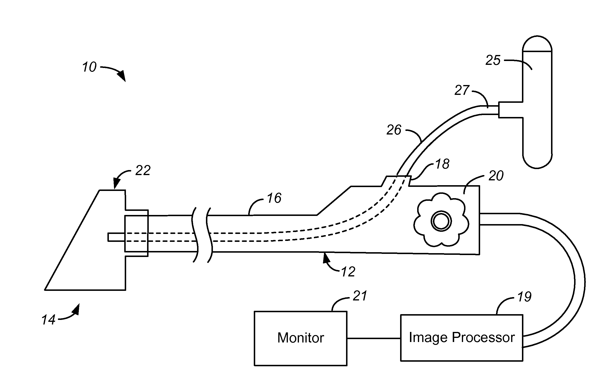
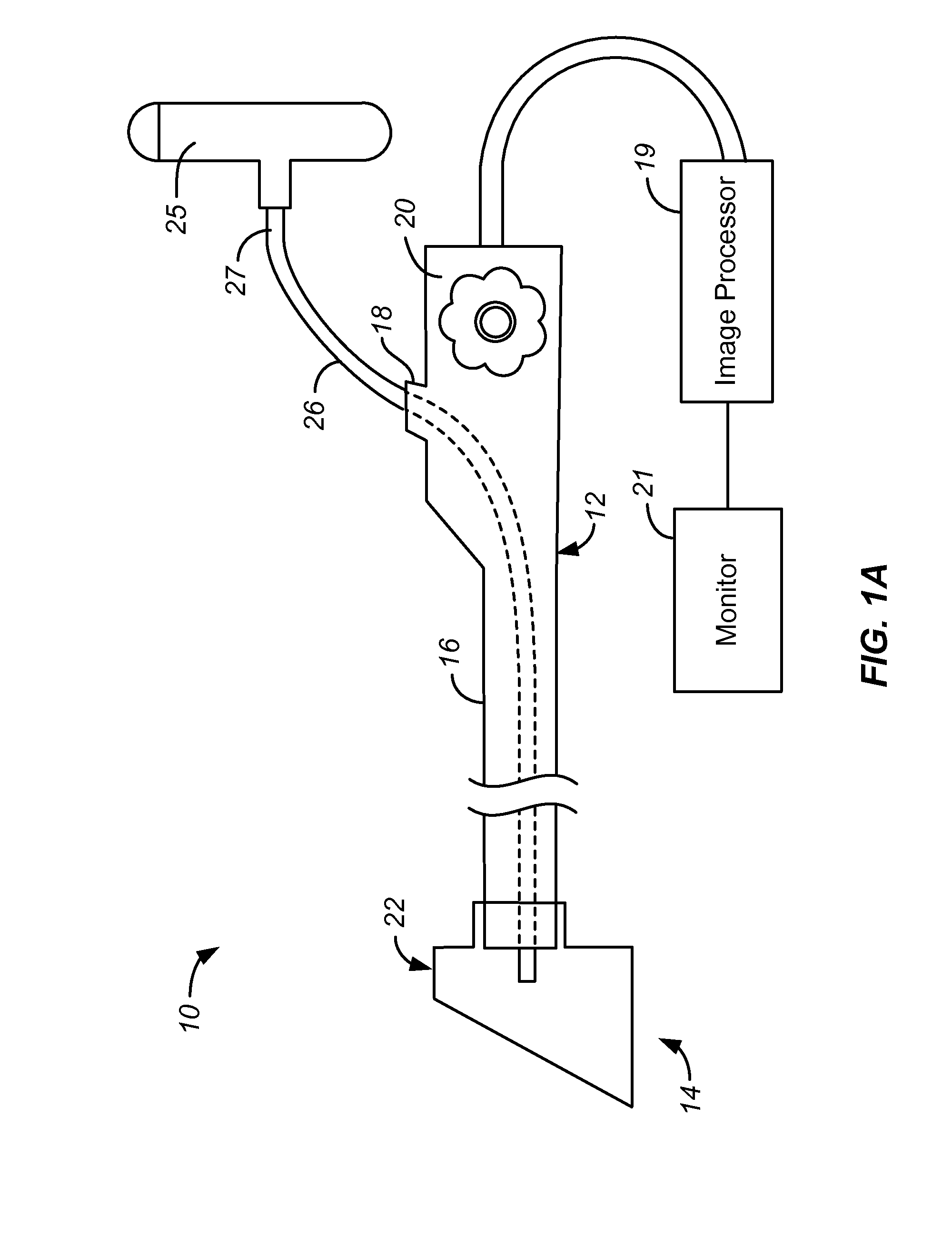
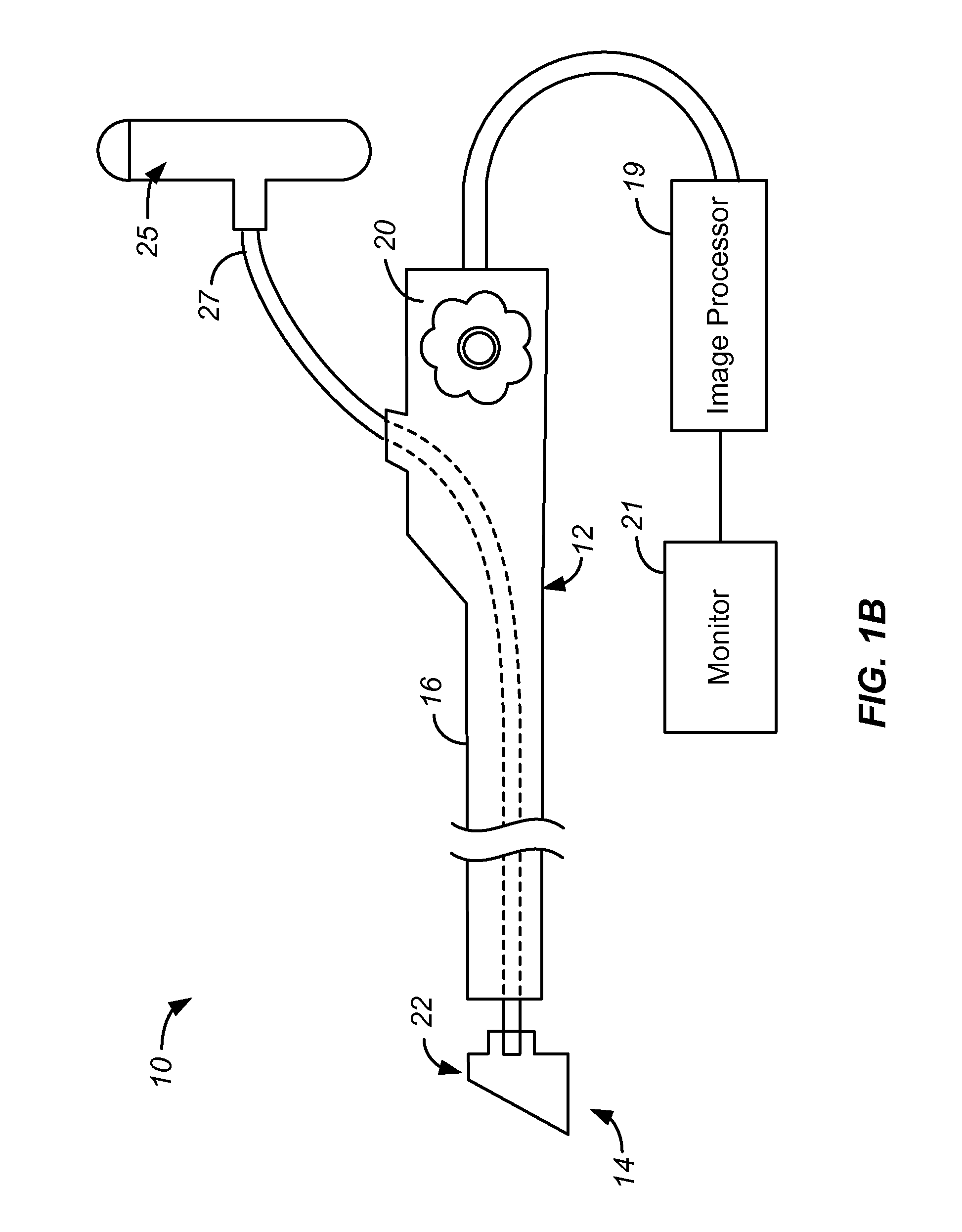
This patent describes a focal ablation assembly for use with an endoscope. The assembly includes a cryogenic catheter and a cap that can be mounted on the endoscope. The cap has a therapeutic region that can be covered or left open. The cap is made of a flexible polymer material and has a limited area that is designed to maintain its shape without causing tissue damage. The cap can be coupled with a delivery catheter to introduce refrigerant into the cap and the therapeutic region. The assembly also includes a balloon for introducing the refrigerant. The technical effect of this invention is the ability to efficiently and safely ablate tissue with a focused treatment using a cryogenic catheter and cap with a therapeutic region that can be covered or left open.

Problems solved by technology

Removal of these tissues through techniques such as Endoscopic Mucosal Resection (EMR) may create unwanted complications such as bleeding and current ablative modalities such as Argon Plasma Coagulation (APC) and Radio Frequency Ablation (RFA) suffer from a variety of drawbacks.
Furthermore, existing cryoablation technologies, which spray the cryogen directly onto the body lumen do not adequately allow control of the energy dosage.

Method used


Image

  • Focal Ablation Assembly
  • Focal Ablation Assembly
  • Focal Ablation Assembly

Examples


Embodiment Construction

[0023]The following description will typically be with reference to specific structural embodiments and methods. It is to be understood that there is no intention to limit the invention to the specifically disclosed embodiments and methods but that the invention may be practiced using other features, elements, methods and embodiments. Preferred embodiments are described to illustrate the present invention, not to limit its scope, which is defined by the claims. Those of ordinary skill in the art will recognize a variety of equivalent variations on the description that follows. Like elements in various embodiments are commonly referred to with like reference numerals.

[0024]The control of three primary factors is necessary for repeatable cryoablation via evaporative cooling. These factors are evaporation temperature of the cryogen, the mass flow rate of the cryogen / surface area, and the amount of time that the cryogen is applied. The present invention directly addresses two of these f...


PUM


Abstract

A focal ablation assembly, used with an endoscope comprising an endoscopic tube, comprises a cap and a cryogenic catheter placeable within the endoscopic tube channel. The cryogenic catheter defines a catheter lumen and has a distal end placeable at the endoscopic tube distal end. The cap is mountable to at least one of the distal ends and extends distally of both. The cap comprises a material which substantially maintains its shape during use while not causing tissue trauma. The cap defines a limited area therapeutic region, which is a chosen one of an open therapeutic region and a covered, effectively thermally transparent therapeutic region providing effectively no thermal insulation. In some examples the assembly includes a delivery catheter extending along the channel with a distal portion fluidly coupled to the cap volume, whereby refrigerant can be introduced into the cap volume and towards the therapeutic region by the delivery catheter.

Description

CROSS-REFERENCE TO OTHER APPLICATIONS[0001]This application is related to the following US patent application publication: US 2010 / 0130970 A1 (attorney docket WILL 1002-2).FEDERALLY SPONSORED RESEARCH OR DEVELOPMENT[0002]None.BACKGROUND OF THE INVENTION[0003]Throughout the GI tract in the human body there are focal lesions of unwanted or unhealthy tissue that physicians desire to remove or ablate in situ. Examples of these lesions include ‘islands’ of intestinal metaplasia and dysplasia in the esophagus or ‘flat’ polyps in the colon. Removal of these tissues through techniques such as Endoscopic Mucosal Resection (EMR) may create unwanted complications such as bleeding and current ablative modalities such as Argon Plasma Coagulation (APC) and Radio Frequency Ablation (RFA) suffer from a variety of drawbacks. Furthermore, existing cryoablation technologies, which spray the cryogen directly onto the body lumen do not adequately allow control of the energy dosage.BRIEF SUMMARY OF THE I...

Claims


Application Information

Patent Timeline
Patent Type & Authority Applications(United States)
IPC IPC(8): A61B18/02
CPCA61B18/02A61B2018/00494A61B2018/0275A61B2018/00982A61B2018/00577
Inventor WU, PATRICK P.ICO, CESAR A.WILLIAMS, RICHARD S.
Owner PENTAX OF AMERICA
Learn More