Rotational atherectomy device with electric motor

a technology of rotational atherectomy and electric motor, which is applied in the field of improvement of rotational atherectomy device having electric motor, can solve the problems of large pneumatic system required for such a device, difficult to achieve the effect of reliable saline delivery and rapid slowing of their rotation

Active Publication Date: 2013-01-17
CARDIOVASCULAR SYST INC
View PDF5 Cites 57 Cited by
  • Summary
  • Abstract
  • Description
  • Claims
  • Application Information

AI Technical Summary

Benefits of technology

[0019]Yet another embodiment is a rotational atherectomy system, comprising: an elongated, flexible drive shaft having a distal end for insertion into a vasculature of a patient and having a proximal end opposite the distal end remaining outside the vasculature of the patient; an eccentric solid crown attached to the drive shaft proximate the distal end of the drive shaft; an electric motor rotatably coupled to the proximal end of the drive shaft, the electric motor being capable of rotating the drive shaft in a first direction and in a second direction opposite the first direction; and control electronics for monitoring and controlling the rotation of the electric motor. The drive shaft and eccentric solid crown, when rotating, have a torque limited by a current supplied to the electric motor. The control electronics include an algorithm that detects and controls when the drive shaft and eccentric solid crown encounter a blockage in the vasculature that rapidly slows their rotation. The control electronics include limits on maximum and minimum rotational speeds of the electric motor. The control electronics include limits on maximum and minimum current supplied to the electric motor. The control electronics include limits on maximum and minimum torque delivered by the electric motor. The control unit includes a void detector that ensures reliable delivery of saline to the vasculature of the patient.

Problems solved by technology

The pneumatic system required for such a device is substantial.
The controller for such an air system is mechanically complicated, and can be quite expensive.

Method used


Image

  • Rotational atherectomy device with electric motor
  • Rotational atherectomy device with electric motor
  • Rotational atherectomy device with electric motor

Examples


Embodiment Construction

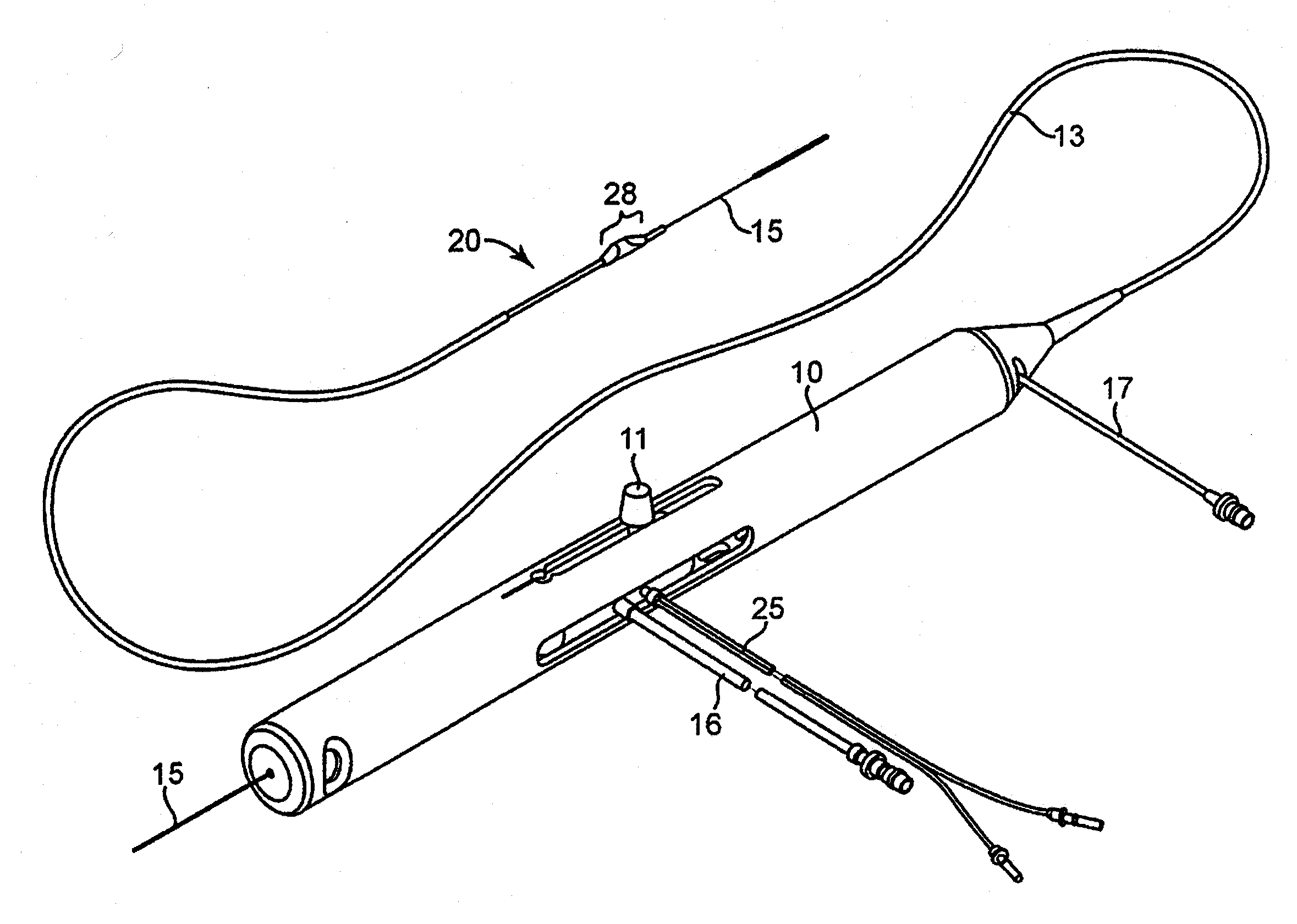
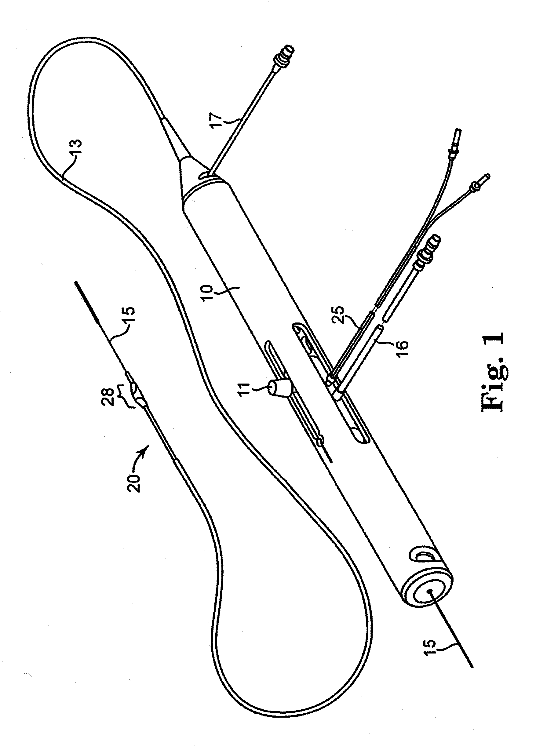
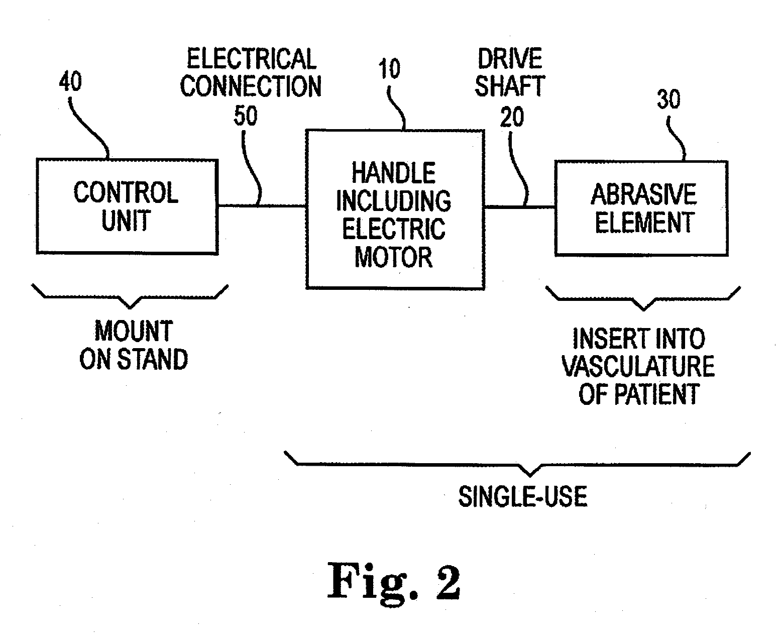
[0033]An atherectomy device is disclosed, which is rotationally driven by an electric motor. In some designs, the device includes features unavailable on gas turbine-driven systems, such as the storing in memory of low / medium / high preset rotation speeds for particular models of handle, calculations of the amount of saline left in the IV and associated warnings when it gets sufficiently low, and automatic adjustment of the IV pump rate to a predetermined or calculated level when the rotational speed of the motor is changed. The electric motor has far more rotational inertia than a comparable gas turbine, so the system includes a control mechanism that helps prevent damage from excessive torque being applied to the distal end of the drive shaft. When an obstruction at the distal end is detected, by a drop in the motor rotational speed, the motor is released and is allowed to spin freely as a flywheel. The freely-spinning motor allows the large angular momentum of the system to dissipa...


PUM


Abstract

An atherectomy device is disclosed, which is rotationally driven by an electric motor. In some designs, the device includes features unavailable on gas turbine-driven systems, such as the storing in memory of low / medium / high preset rotation speeds for particular models of handle, calculations of the amount of saline left in the IV and associated warnings when it gets sufficiently low, and automatic adjustment of the IV pump rate to a predetermined or calculated level when the rotational speed of the motor is changed. The electric motor has far more rotational inertia than a comparable gas turbine, so the system includes a control mechanism that helps prevent damage from excessive torque being applied to the distal end of the drive shaft. When an obstruction at the distal end is detected, by a drop in the motor rotational speed, the motor is released and is allowed to spin freely as a flywheel. The freely-spinning motor allows the large angular momentum of the system to dissipate rapidly and safely, without excessive torque to the drive shaft.

Description

CROSS-REFERENCE TO RELATED APPLICATIONS[0001]Not ApplicableSTATEMENT REGARDING FEDERALLY SPONSORED RESEARCH OR DEVELOPMENT[0002]Not ApplicableBACKGROUND OF THE INVENTION[0003]1. Field of the Invention[0004]The invention relates to devices and methods for removing tissue from body passageways, such as removal of atherosclerotic plaque from arteries, utilizing a rotational atherectomy device. In particular, the invention relates to improvements in a rotational atherectomy device having an electric motor.[0005]2. Description of the Related Art[0006]Atherectomy is a non-surgical procedure to open blocked coronary arteries or vein grafts by using a device on the end of a catheter to cut or shave away atherosclerotic plaque (a deposit of fat and other substances that accumulate in the lining of the artery wall). For the purposes of this application, the term “abrading” is used to describe the grinding and / or scraping action of such an atherectomy head.[0007]Atherectomy is performed to res...

Claims


Application Information

Patent Timeline
Patent Type & Authority Applications(United States)
IPC IPC(8): A61B17/22
CPCA61B17/320758A61B2017/00075A61B2019/466A61B2017/320004A61B2017/320766A61B2017/00199A61B2090/066
Inventor RIVERS, JODY LEEPLOWE, CHARLES A.PIIPPO SVENDSEN, CASSANDRA ANNDOBROVOLNY, WALTER JOHNENG, MICHAEL JOHNHANSON, SCOTT M.
Owner CARDIOVASCULAR SYST INC
Why Eureka
Try Eureka