
Method And System For Time Synchronization Of Phase Of Signals From Respective Measurement Devices

a technology of phase synchronization and measurement device, which is applied in the direction of structural/machine measurement, instruments, and using reradiation, etc., and can solve problems such as limiting the strategies for noise reduction

Active Publication Date: 2013-01-17
HYDRO QUEBEC CORP
View PDF0 Cites 40 Cited by
  • Summary
  • Abstract
  • Description
  • Claims
  • Application Information

AI Technical Summary

Benefits of technology

The invention is a system and method for synchronizing phase measurements in different areas such as electricity transport networks, industrial control, vibration measurement, and localization. The invention uses a system of distributed measurements and requires high precision in the synchronization of the measured phase. The invention provides a low-cost solution and allows economical monitoring of the dielectric state of transformer bushings. It also allows precise synchronization of different equipment located at different locations and precise estimation of the orientation of one or several wave fronts from a distribution of stationary or moving receivers. The invention involves several phase measurement units and at least one phase processing unit, and the method involves digitizing the signal from the sensor, receiving the synchronization signal and reference clock, incrementing the counter, and resetting the counter.

Problems solved by technology

This approach requires equipment achieving a feedback (phase-lock-loop) between the phase of the sampling clock and the time reference, which results in costs.
Furthermore, this approach limits the strategies for noise reduction since the noise of the sampling clock and that of the reference clock are mixed with the clock drive errors.

Method used


Image

  • Method And System For Time Synchronization Of Phase Of Signals From Respective Measurement Devices
  • Method And System For Time Synchronization Of Phase Of Signals From Respective Measurement Devices
  • Method And System For Time Synchronization Of Phase Of Signals From Respective Measurement Devices

Examples


Embodiment Construction

[0101]As used in connection with this disclosure, the term “temporal characteristic” designates a frequency, a scale, a periodicity or a similar parameter of a component of interest of a signal.

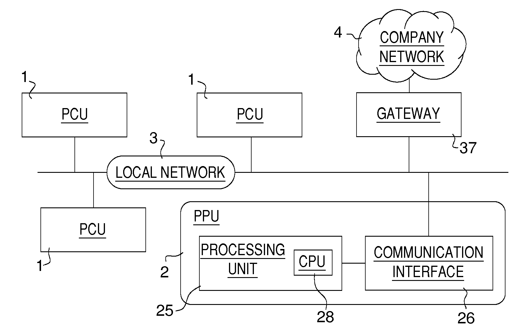
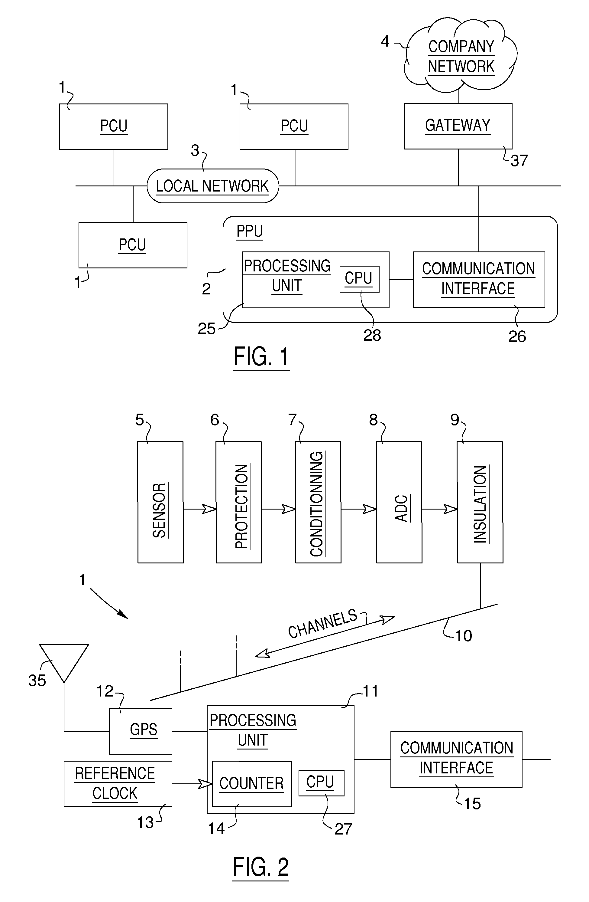
[0102]Referring to FIG. 1, there is shown an example of architecture of a system according to the invention where several phase measurement units 1 (also called hereinafter phase computing units or PCUs) are connected to a phase processing unit or PPU 2 via a local communication network 3 that may itself be connected to a larger network 4. Other PCUs (not shown) may also be added through the larger network 4. In a possible configuration of the system according to the invention, the role of each PCU 1 is to estimate amplitude, phase and frequency values of one or several spectral components of a measured signal while associating a time tag to these data, whereas the role of the PPU 2 is to process the data derived from the PCUs 1 in order to regroup them under like time tags to achieve the tim...


PUM


Abstract

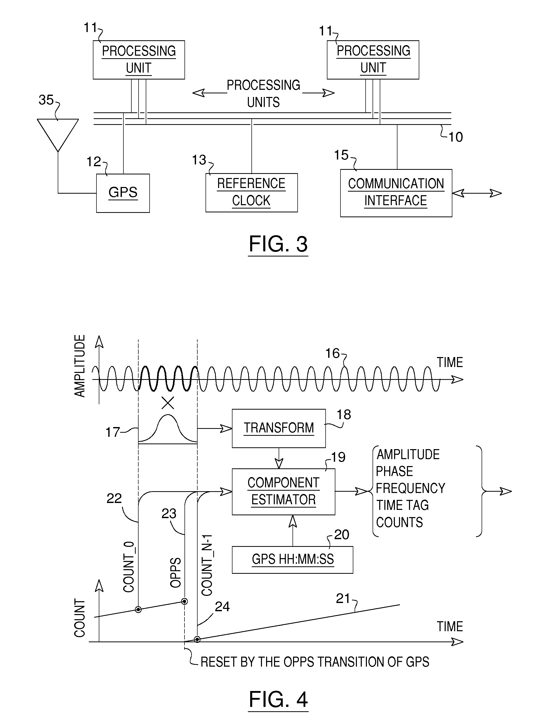
According to the invention, a time synchronization of phase between measurement devices that do not share a same clock for their respective sampling of the signals is carried out by a time tagging of samples of the signals in time blocks followed by an adjustment of the phase values of components of interest of the signals in the regrouped time blocks so that the values refer to common time references between the measurement devices. The tagging is carried out with a synchronization signal available to the measurement devices, completed with count values provided by a counter operated by a reference clock for each measurement device.

Description

CROSS-REFERENCE TO RELATED APPLICATIONS[0001]The present application is a continuation of pending International patent application PCT / CA2011 / 050143 filed on Mar. 16, 2011 which designates the United States and claims priority from Canadian patent application 2,699,596 filed on Mar. 24, 2010. The content of all prior applications is incorporated herein by reference.FIELD OF THE INVENTION[0002]The invention relates to a method and a system for time synchronization of phase of signals from respective measurement devices.BACKGROUND OF THE INVENTION[0003]Various systems, processes and techniques require carrying out a time synchronization of phase measurements between different converting devices that do not share a same clock signal for their respective sampling. Many of the existing systems perform a sampling by a clock locked on a common time reference. This approach requires equipment achieving a feedback (phase-lock-loop) between the phase of the sampling clock and the time referen...

Claims


Application Information

Patent Timeline
IPC IPC(8): G06F19/00G06F17/18
CPCG01M5/00G01S7/40G01D21/00G01D9/005G01S13/003
Inventor RIENDEAU, SYLVAINLEONARD, FRANCOISPICHER, PATRICKGAUVIN, MICHELBERTRAND, HUGODUPONT, LOUIS
Owner HYDRO QUEBEC CORP
Learn More