Continuous gas carburizing furnace

a carburizing furnace and gas technology, applied in furnaces, heat treatment equipment, lighting and heating equipment, etc., can solve the problems of difficult to secure high precision quality (product accuracy), large equipment cost, and likely local distortion, and achieve low cost, small installation space, and high productivity.

Inactive Publication Date: 2013-01-24
TOYOTA JIDOSHA KK +1
View PDF2 Cites 8 Cited by
  • Summary
  • Abstract
  • Description
  • Claims
  • Application Information

AI Technical Summary

Benefits of technology

[0025]The invention provides a continuous gas carburizing furnace that is capable of arbitrary selection between gas quenching and oil quenching, and that requires only a small installation space, and does not require a large amount of equipment cost, and achieves high productivity, and has a simple construction, and that has high reliability as the entire equipment.
[0034]That is, according to the continuous gas carburizing furnace of the invention, it is possible to provide a continuous gas carburizing furnace that is capable of arbitrary selection between gas quenching and oil quenching and that requires only a small installation space, and does not require a large amount of equipment cost, and achieves high productivity, and has a simple construction, and that has high reliability as the entire equipment.

Problems solved by technology

However, since the workpieces are rapidly cooled in a short time, local distortion is likely to occur, and high precision quality (product accuracy) is difficult to secure.
On the other hand, in the gas quenching, workpieces are cooled by a gas, that is, an inert gas (nitrogen gas), so that a longer cooling time is required than in the oil quenching, and therefore lower productivity results.
However, since workpieces are cooled gradually as a whole, local distortion is unlikely to occur, and high precision quality (product accuracy) can be secured.
As a result, the productivity of the cell-type reduced-pressure carburizing furnace 201 as a whole is rather low.
Therefore, a large installation space is needed, and the equipment-occupied area (i.e., the area of an installation space for one workpiece becomes large, so that the equipment cost increases.
Furthermore, in the vacuum conveying chamber 202, the flow lines (shown by the arrows 1 to 5 in FIG. 12A) representing the movements from one cell to another is complicated and intertangled, so that a complicated construction of the conveying mechanism results.
Thus, the equipment cost increases.
However, the conveying devices 304, which each convey the gas quenching chamber 305 or the oil quenching chamber 306 independently from each other, have a long and large construction, and also have a complicated structure.
Therefore, the equipment cost increases.
Therefore, the equipment occupied area (i.e., the area of the installation space per workpiece) becomes large, so that the equipment cost increases.
An apparatus for creating such a vacuum state requires a complicated construction, which makes it difficult to secure reliability of the furnace equipment as a whole.
In such a case, the moving time of the gas quenching chamber 305 or the oil quenching chamber 306 is long, so that a large amount of heat for keeping the temperature of workpieces is consumed in order to restrain variations of the product accuracy, resulting in increased running cost.

Method used


Image

  • Continuous gas carburizing furnace
  • Continuous gas carburizing furnace
  • Continuous gas carburizing furnace

Examples


Embodiment Construction

[0048]An embodiment of the invention will be hereinafter described.

[Overall Construction of Continuous Gas Carburizing Furnace 1]

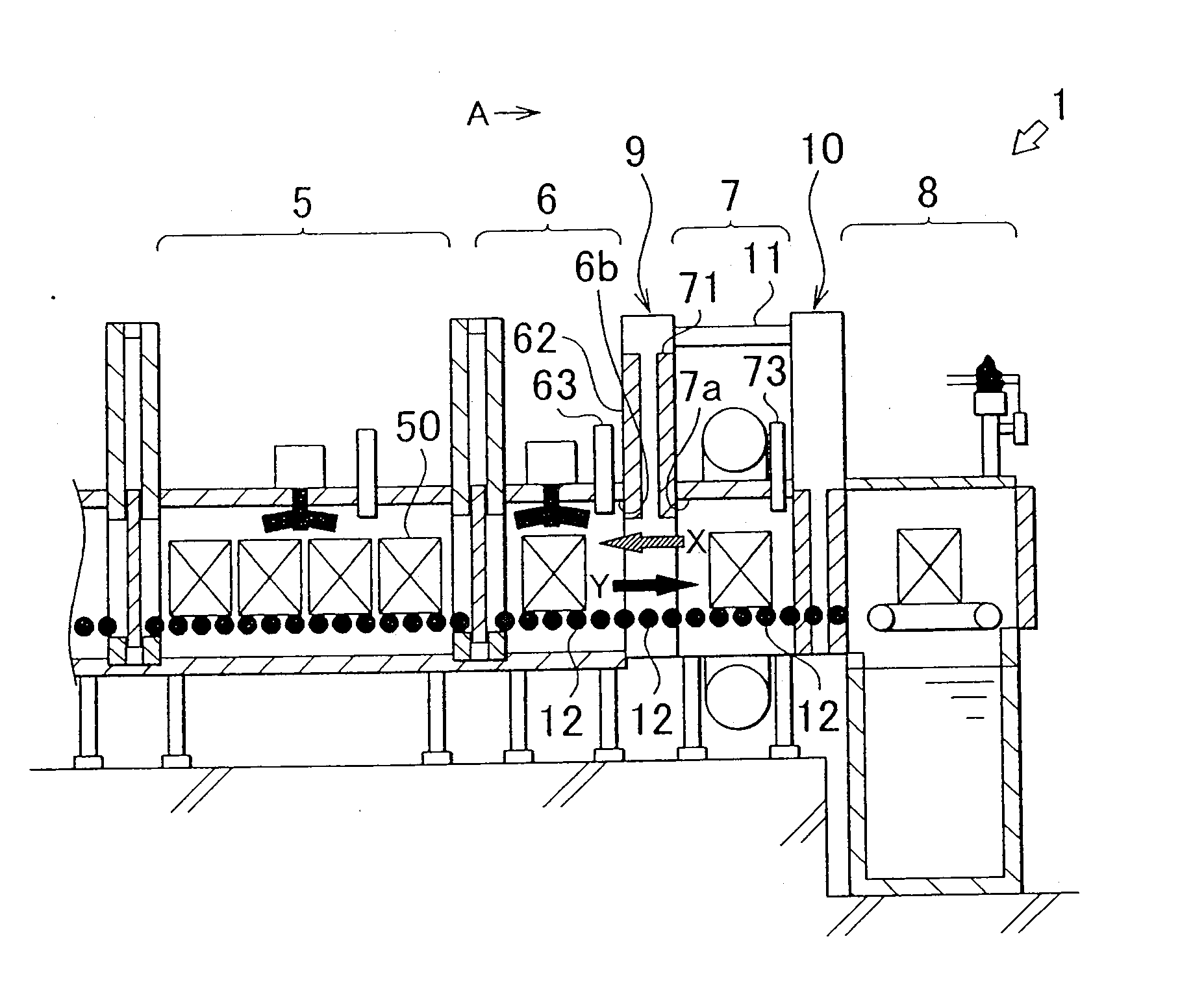
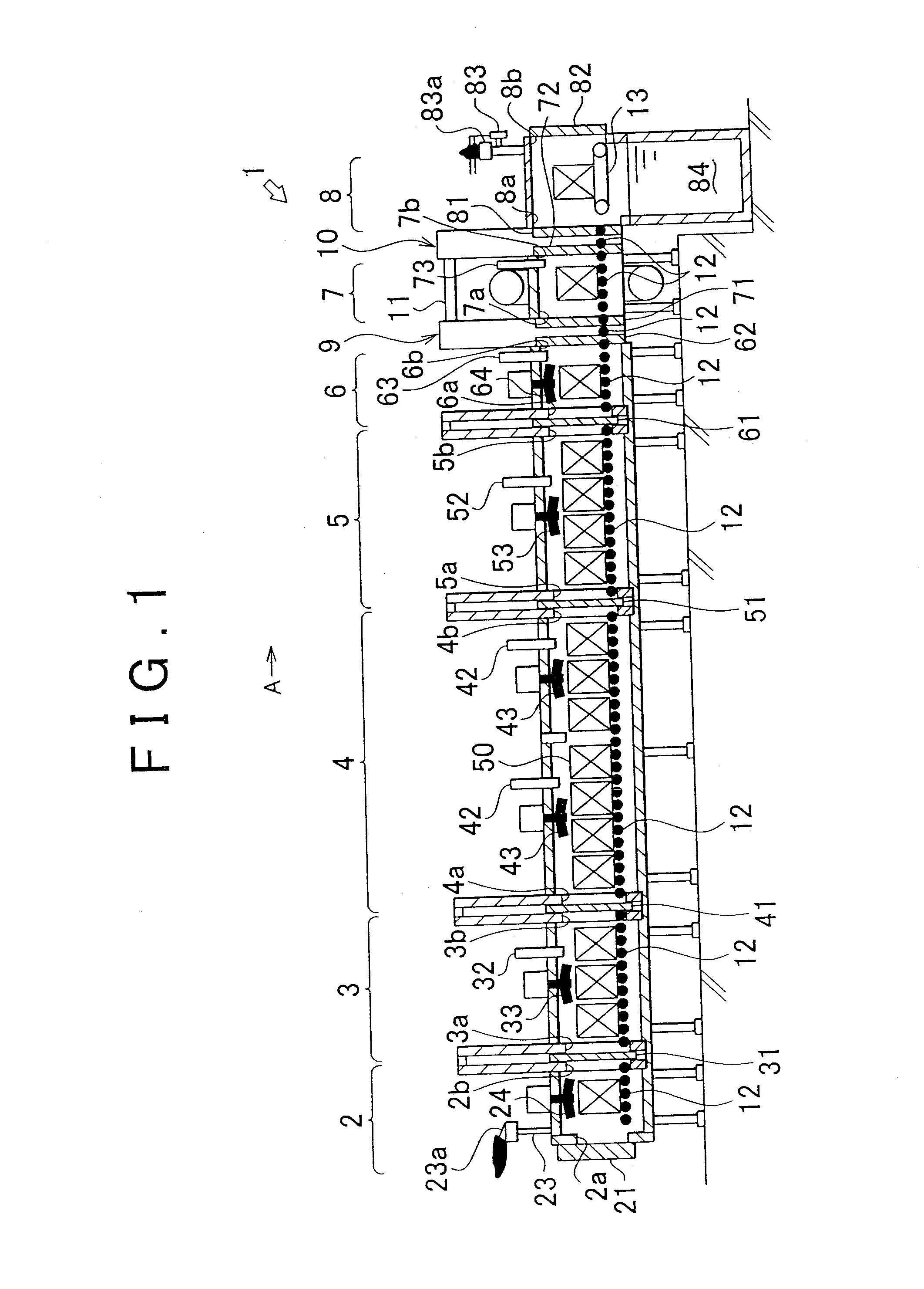
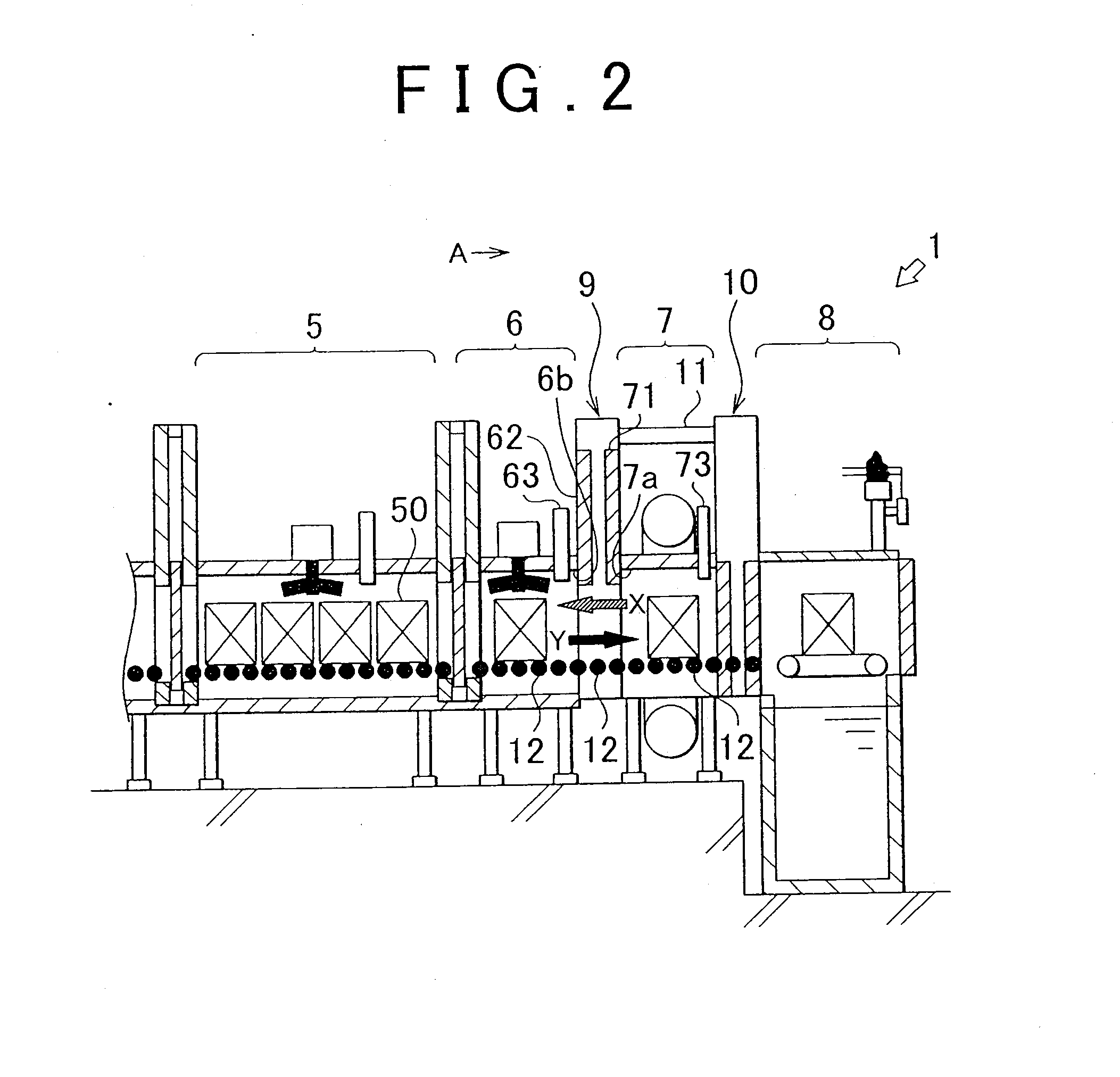
[0049]Firstly, an overall construction of a continuous gas carburizing furnace 1 in accordance with an embodiment of the invention will be described with reference to FIG. 1 Incidentally, for the following description, it is assumed that the direction of an arrow A in FIG. 1 shows the conveying direction of workpieces 50; and defines the forward direction of the continuous gas carburizing furnace 1.

[0050]The continuous gas carburizing furnace 1 has a preheating chamber 2, a heating chamber 3, a carburizing chamber 4, a diffusion chamber 5, temperature decrease chamber 6, a gas quenching chamber 7, an oil quenching chamber 8, a first conveying chamber 9 disposed between the temperature decrease chamber 6 and the gas quenching chamber 7, and a second conveying chamber 10 disposed between the gas quenching chamber 7 and the oil quenching chamber 8. These cham...


PUM

PropertyMeasurementUnit
temperatureaaaaaaaaaa

Abstract

A continuous gas carburizing furnace includes a gas carburizing processing chamber (a preheating chamber 2, a heating chamber 3, a carburizing chamber 4, a diffusion chamber 5 and a temperature decrease chamber 6) in which a gas carburizing process is performed on a workpiece 50, an oil quenching chamber 8 in which oil quenching is performed on the workpiece 50, and a gas quenching chamber 7 in which gas quenching is performed on the workpiece 50. The gas carburizing processing chamber includes a temperature decrease chamber 6 in which the temperature of the workpiece heated by a gas carburizing process is lowered. The temperature decrease chamber 6, the gas quenching chamber 7 and the oil quenching chamber 8 are arranged in that order from the upstream side to the downstream side in the conveying direction of the workpiece 50, and are adjacent to each other.

Description

BACKGROUND OF THE INVENTION[0001]1. Field of the Invention[0002]The invention relates to a technology of a continuous gas carburizing furnace capable of arbitrary selection between gas quenching and oil quenching.[0003]2. Description of the Related Art[0004]A known method of surface hardening performed on a steal material (hereinafter, termed “workpiece”) according to the related art is a carburizing process. The carburizing process is a method in which a surface of a workpiece is infiltrated with carbon (carburized) and the carbon in the surface is diffused so as to increase the amount of carbon in the surface, and then quenching is performed so as to improve the abrasion resistance of the workpiece's surface while securing toughness of the workpiece.[0005]Among the carburizing processes, a gas carburizing method that uses a carburizing gas (CO gas) as a carburizing agent is known. In fact, a carburizing process that uses a continuous gas carburizing furnace is often employed becau...

Claims


Application Information

Patent Timeline
Patent Type & Authority Applications(United States)
IPC IPC(8): B05C11/00
CPCC21D1/58C21D1/613C21D1/74C21D1/76C23C8/20F27D2009/0089F27B9/045F27D2009/0072F27D2009/0075F27D2009/0081F27B9/04
Inventor YAMADA, MASAHIROOOSHITA, OSAMUTOOYAMA, KAZUNORIKONO, YUKI
Owner TOYOTA JIDOSHA KK
Why Eureka
Try Eureka