Power converter apparatus and method with compensation for current limit/current share operation

Active Publication Date: 2013-01-24
CRANE ELECTRONICS INC
View PDF4 Cites 48 Cited by
  • Summary
  • Abstract
  • Description
  • Claims
  • Application Information

AI Technical Summary

Benefits of technology

[0009]New approaches to providing power converters which can satisfy the demands for high curren

Problems solved by technology

Existing approaches for controlling an output current of a power converter to accomplish current limiting and to force multiple power converters to share the output load current are not as efficient as might otherwise be desired.
These approaches are associated with significant issues, for instance lower sensitivity, lower efficiency, and the need for high common mode rejection due to the wide (e.g., 4:1) range of the output voltage or potential.
Additionally, there are a variety of problems in implementing a current limit/current share

Method used


Image

  • Power converter apparatus and method with compensation for current limit/current share operation
  • Power converter apparatus and method with compensation for current limit/current share operation
  • Power converter apparatus and method with compensation for current limit/current share operation

Examples


Example

[0038]In the following description, certain specific details are set forth in order to provide a thorough understanding of various disclosed embodiments. However, one skilled in the relevant art will recognize that embodiments may be practiced without one or more of these specific details, or with other methods, components, materials, etc. In other instances, well-known structures associated with power conversion topologies have not been shown or described in detail to avoid unnecessarily obscuring descriptions of the embodiments.

[0039]Unless the context requires otherwise, throughout the specification and claims which follow, the word “comprise” and variations thereof, such as, “comprises” and “comprising” are to be construed in an open, inclusive sense, that is as “including, but not limited to.”

[0040]Reference throughout this specification to “one embodiment” or “an embodiment” means that a particular feature, structure or characteristic described in connection with the embodimen...


PUM


Abstract

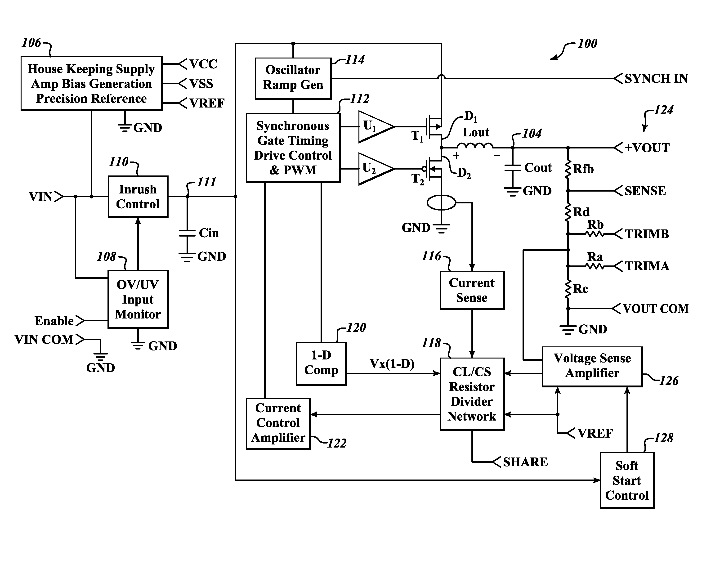
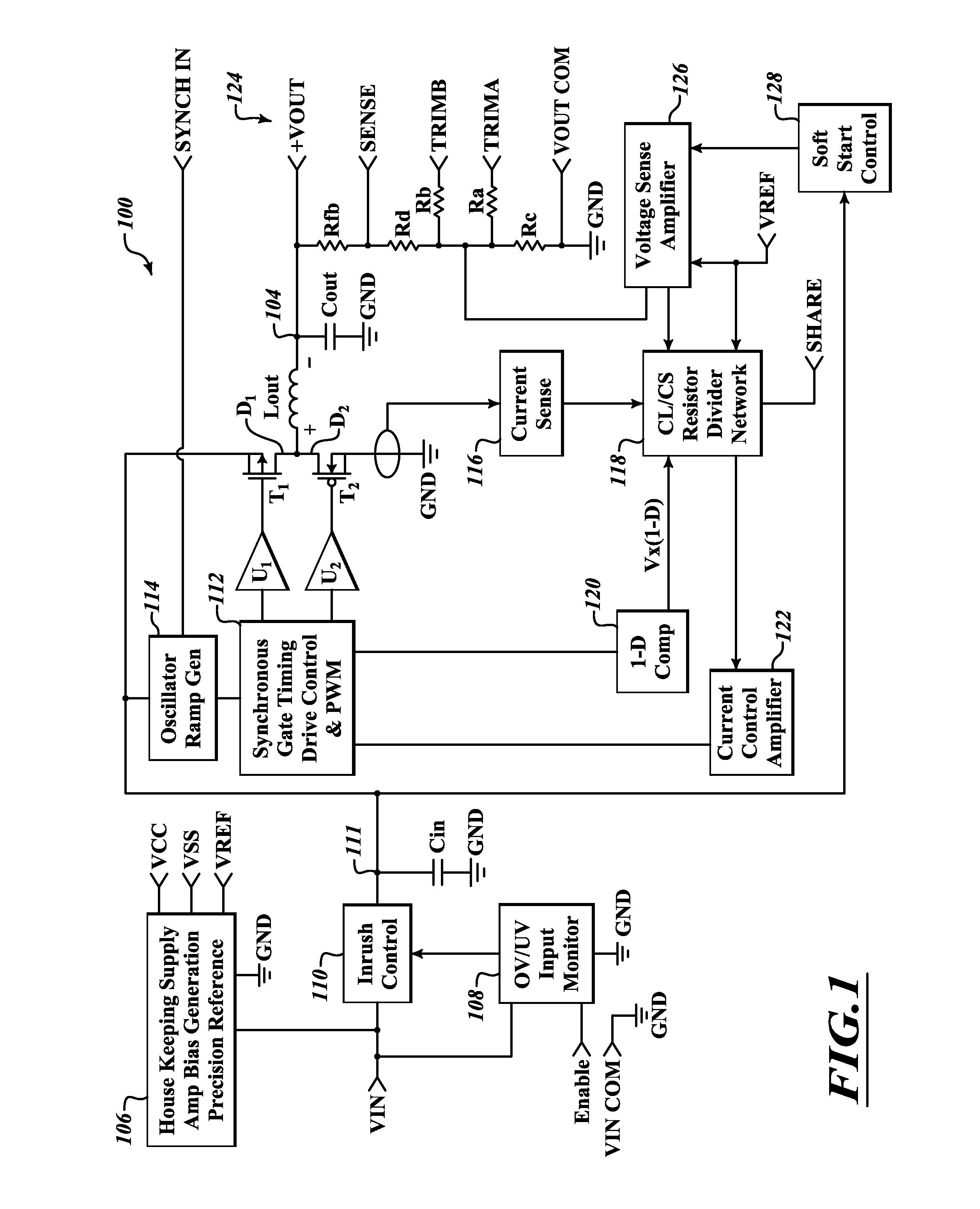
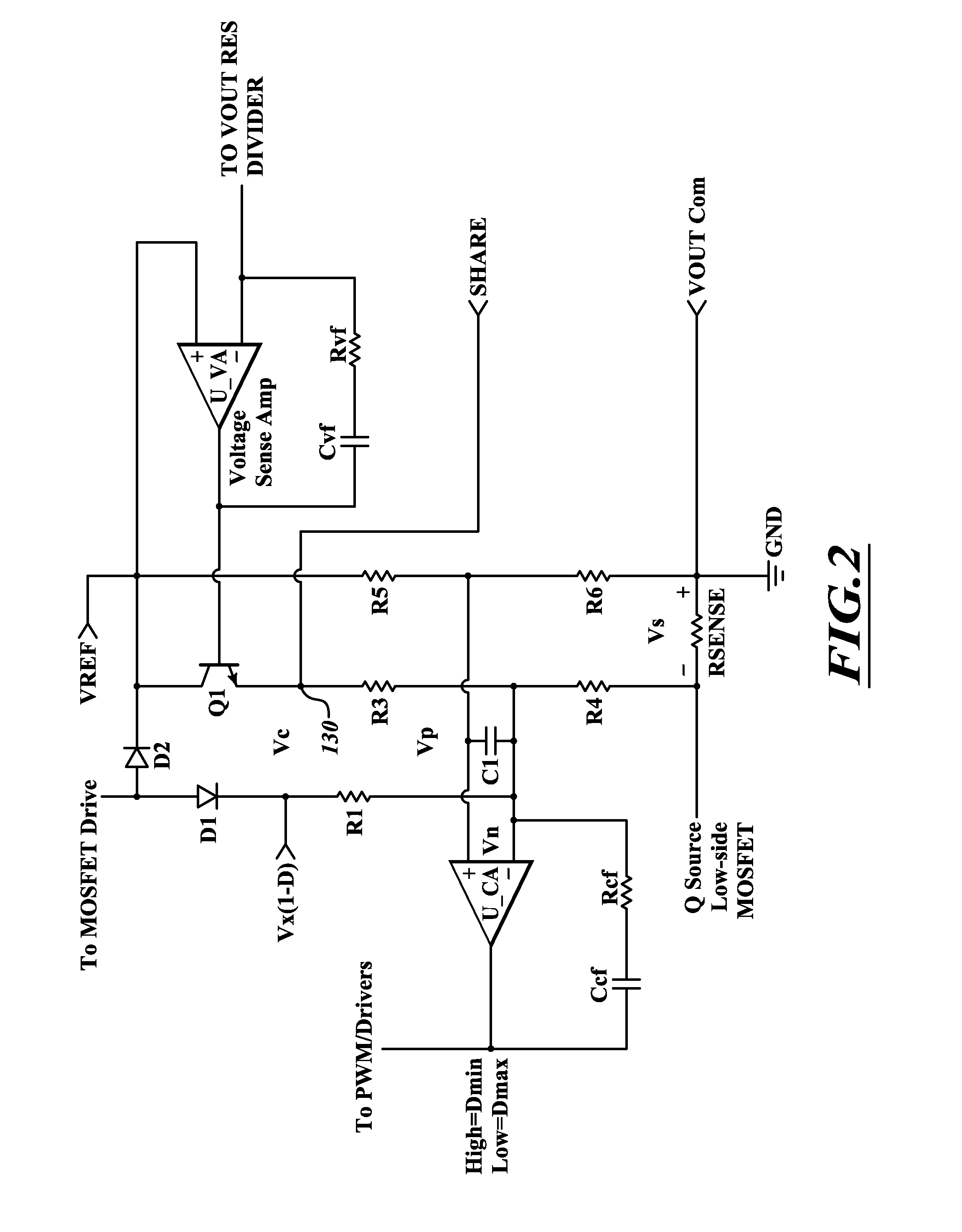
A power converter provides current limit/current share functionality, allowing use in a point-of-load architecture and/or in parallel with one or more other power converters. An inner current control loop may sense output current over only a portion of a duty cycle, for example at a low side active switch. The resulting signal is compensated, and may be level shifted, for example via a resistor divider network, and supplied to a current control amplifier. An outer voltage control loop may sense output voltage, and provide a voltage error signal from a voltage error amplifier to the resistor divider network. Power converters are operable as masters or slaves, and include sense input and trim input terminals.

Description

BACKGROUND[0001]1. Technical Field[0002]This disclosure is generally related to power converters, and is more particularly related to regulated power converters.[0003]2. Description of the Related Art[0004]Power converters are used to transform electrical energy, for example converting between alternating current (AC) and direct current (DC), adjusting (e.g., stepping up, stepping down) voltage levels and / or frequency.[0005]Power converters take a large variety of forms. One of the most common forms is the switched-mode power converter or supply. Switched-mode power converters employ a switching regulator to efficiently convert voltage or current characteristics of electrical power. Switched-mode power converters typically employ a storage component (e.g., inductor, transformer, capacitor) and a switch that quickly switches between full ON and full OFF states, minimizing losses. Voltage regulation may be achieved by varying the ratio of ON to OFF time or duty cycle. Various topologi...

Claims


Application Information

Patent Timeline
IPC IPC(8): G05F1/00
CPCH02M3/156H02M2001/0025H02M2001/0009H02M3/1584H02M1/0009H02M1/0025
Inventor WALTMAN, BARRY F.ADRIANCE, REIDKUEHNY, JAY ALLENKRISTJANSSON, STEFAN JON
Owner CRANE ELECTRONICS INC
Why Eureka
Try Eureka