Electrostatic chuck

a technology of electrostatic chucks and chucks, applied in the direction of electrostatic holding devices, manufacturing tools, mechanical apparatus, etc., can solve problems such as inability to mitigate, and achieve the effect of suppressing crack generation and rapid heat and cooling of processing target substrates

Inactive Publication Date: 2013-01-31
TOTO LTD
View PDF5 Cites 43 Cited by
  • Summary
  • Abstract
  • Description
  • Claims
  • Application Information

AI Technical Summary

Benefits of technology

[0072]According to the invention, an electrostatic chuck that can rapidly heat and cool a processing target substrate while suppressing crack generation in the ceramic plate is realized.

Problems solved by technology

However, thinning the bonding agent can lead to the inability to mitigate deviance between the metal base substrate and the ceramic plate generated by either a temperature difference between the metal base substrate and the ceramic plate or by a difference in the thermal expansion coefficient between the metal base substrate and the ceramic plate due to the bonding agent thereby reducing the adhesive force thereof.

Method used


Image

  • Electrostatic chuck
  • Electrostatic chuck
  • Electrostatic chuck

Examples


Embodiment Construction

[0082]Detailed embodiments will be described hereinafter with reference to drawings. The embodiment described below also includes a description of means for resolving the problem given above.

[0083]First, descriptions will be given of terms used in the embodiment of the invention.

(Ceramic Plate)

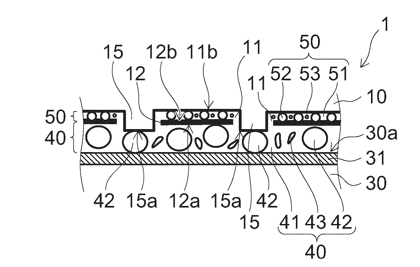
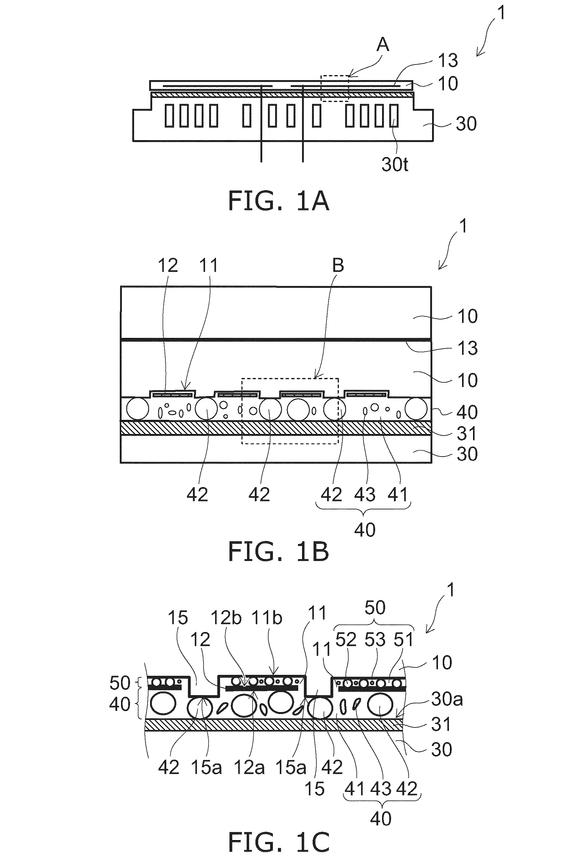
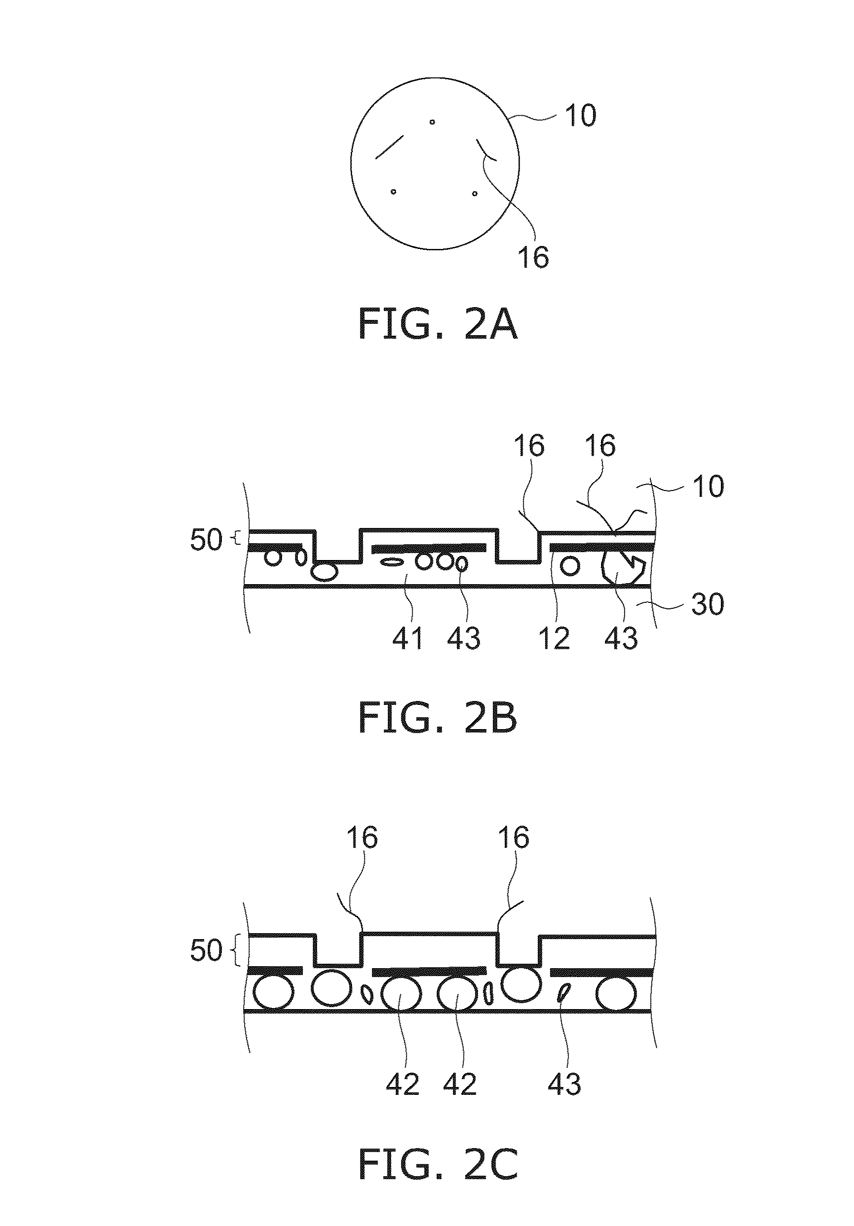
[0084]The ceramic plate is the stage of the electrostatic chuck on which the processing target substrate is placed. The ceramic plate is a ceramic sintered material designed with a uniform thickness. The flatness of the major surface of the ceramic plate is designed to be a predetermined range. If the respective thickness is uniform or the flatness of the respective major surface is secured, then it is unlikely that local stress will be applied to the ceramic plate at the time of hot press curing of the bonding agent. Further, the thickness of the bonding agent interposed between the ceramic plate and the temperature regulating plate can be controlled by the average diameter of the spherical f...


PUM

PropertyMeasurementUnit
diameteraaaaaaaaaa
thicknessaaaaaaaaaa
surface roughnessaaaaaaaaaa

Abstract

An electrostatic chuck comprises: a ceramic plate provided with recesses on a major surface and provided with an electrode in an inner part of the ceramic plate; a temperature regulating plate bonded to the major surface of the ceramic plate; a first bonding agent provided between the ceramic plate and the temperature regulating plate; and a heater provided in the each of the recesses of the ceramic plate. The first bonding agent has a first major agent including an organic material, a first amorphous filler including an inorganic material, and a first spherical filler including an inorganic material. The first amorphous filler and the first spherical filler are dispersion-compounded into the first major agent. The first major agent, the first amorphous filler, and the first spherical filler are made of an electrically insulating material. An average diameter of the first spherical filler is greater than a maximum value of a minor axis of the first amorphous filler. A thickness of the first bonding agent is greater than or equal to the average diameter of the first spherical filler. A width of the each of the recesses is greater than a width of the heater, and a depth of the each of the recesses is greater than a thickness of the heater. The heater is adhered within the each of the recesses by a second bonding agent. A first distance between a major surface of the heater on the side of the temperature regulating plate and a major surface of the temperature regulating plate is greater than a second distance between the major surface between the recesses of the ceramic plate and the major surface of the temperature regulating plate.

Description

TECHNICAL FIELD[0001]The invention relates to an electrostatic chuck.BACKGROUND ART[0002]Electrostatic chucks are used in processes to treat processing target substrates within a vacuum chamber as means for clamping a processing target substrate. In recent years, processes that use high density plasma for the purpose of reducing tact time have become common. Therefore, methods for efficiently removing thermal flux from the high density plasma that inflows to the processing target substrate to outside the electrostatic chuck are required.[0003]For example, a structure is disclosed in which a thermal regulator is bonded by a bonding agent to the bottom side of an electrostatic chuck (for example, see Patent Literature 1). In this structure, a ceramic plate with an electrode is adhered by a rubber, or the like, bonding agent to the top of a metal base substrate of a conductor. Thermal flux that has flowed into the processing target substrate passes through the electrostatic chuck and i...

Claims


Application Information

Patent Timeline
Patent Type & Authority Applications(United States)
IPC IPC(8): H01L21/683
CPCY10T279/23H01L21/6833B23Q3/15H01L21/683H02N13/00
Inventor HORI, HIROAKIKONDO, SHUNPEIANAI, YUKIITAKURA, IKUOUCHIMURA, TAKESHIANADA, KAZUKI
Owner TOTO LTD
Why Eureka
Try Eureka