Electronic endoscope apparatus and electronic endoscope system

a technology of electronic endoscope and endoscope, which is applied in the field of electronic endoscope apparatus and electronic endoscope system, can solve the problems of overcurrent flow, heat generation, and increase of image signal noise,

Inactive Publication Date: 2013-01-31
FUJIFILM CORP
View PDF3 Cites 33 Cited by
  • Summary
  • Abstract
  • Description
  • Claims
  • Application Information

AI Technical Summary

Benefits of technology

[0012]The present invention has been made in view of the above-mentioned problems and an object of the present invention is to provide an electronic endoscope apparatus and an electronic endoscope system that, even in a case where the type of scope is changed, can supply electric power of a required voltage to an endoscope distal end portion, can suppress heat generation of the distal end portion, and can prevent a distal end temperature from reaching a temperature higher than an allowable temperature.
[0014]According to the present invention, the regulators are respectively arranged at the first circuit part built in the endoscope distal end portion and the second circuit part connected to the first circuit part via the cable, and in a case where an abnormality of the distal end portion is detected, output operation of the first regulator or the second regulator or output operation of both the regulators is stopped, and supply of power to the imaging device of the distal end portion is stopped. This can suppress heat generation of the distal end portion. By stopping supply of power to the distal end portion by the abnormality detection, the abnormal state does not last for a long time, and a failure of an electronic circuit can be prevented.
[0030]According to this aspect, the influence of a voltage drop by the cable can be compensated for, and an input voltage to the first regulator can be maintained at a desired value. This can suppress wasteful heat generation in the case of voltage conversion by the first regulator.
[0038]According to the present invention, electric power of a proper voltage can be supplied to the distal end portion of the endoscope insertion part, and a distal end temperature can be prevented from reaching a temperature higher than an allowable temperature.

Problems solved by technology

If the internal temperature of the endoscope insertion part rises, the noise of the image signals increases and the image quality deteriorates.
Additionally, due to a failure of a circuit in the distal end portion etc., overcurrent may flow and heat may be generated.

Method used


Image

  • Electronic endoscope apparatus and electronic endoscope system
  • Electronic endoscope apparatus and electronic endoscope system
  • Electronic endoscope apparatus and electronic endoscope system

Examples


first embodiment

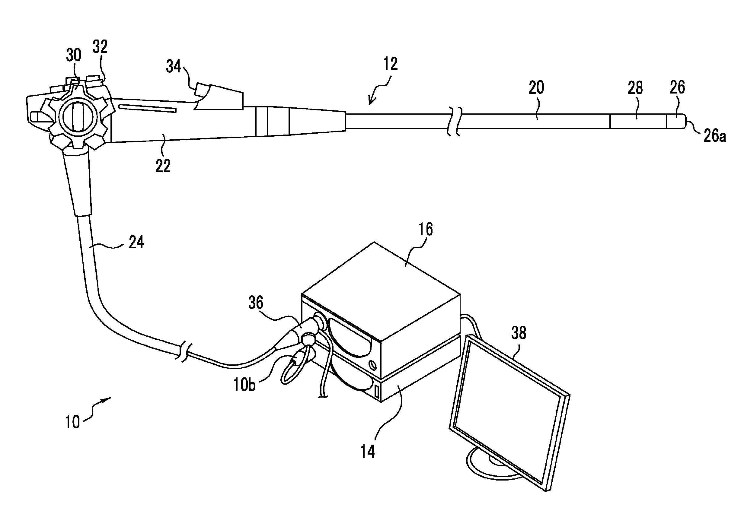
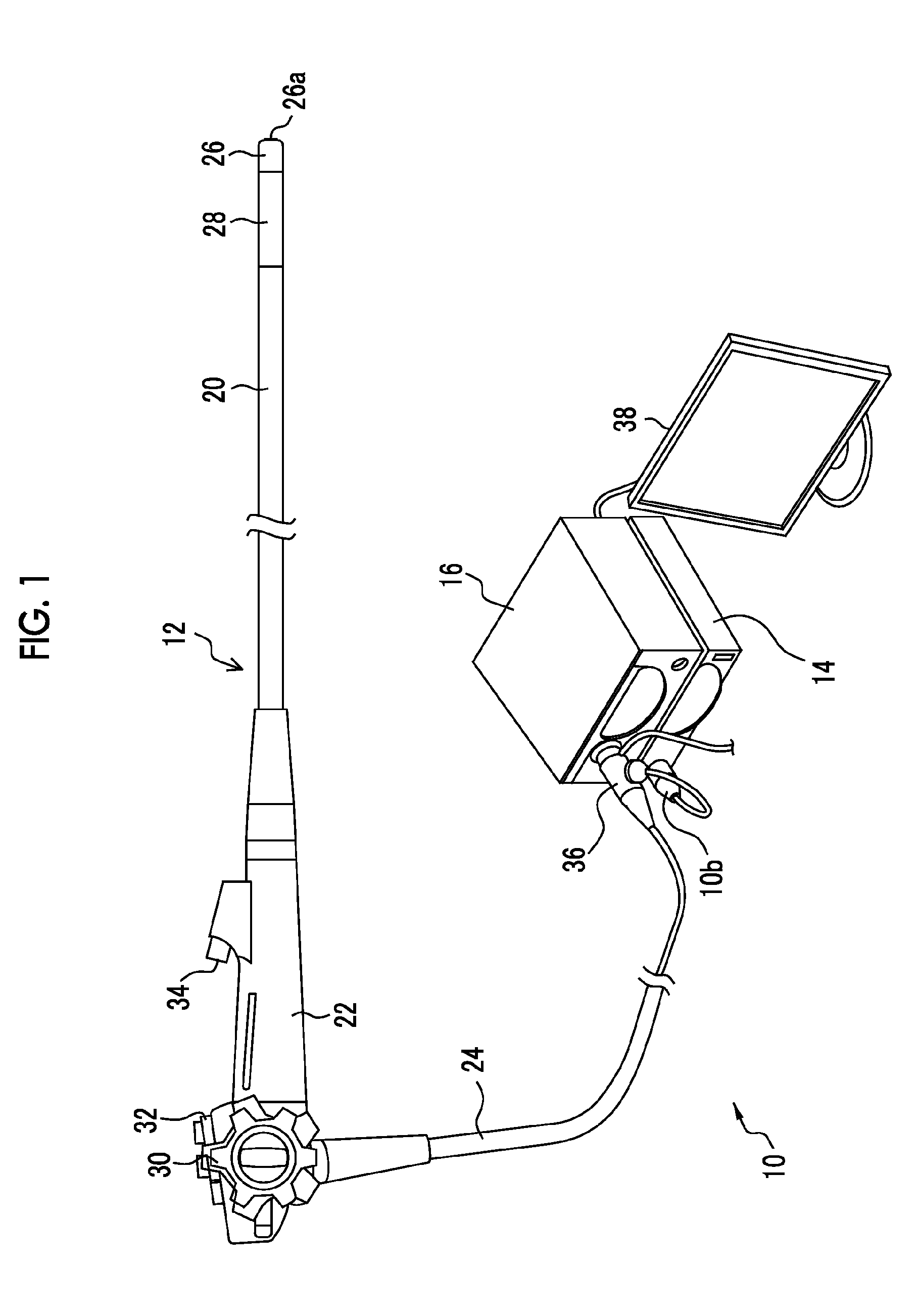
[0049]FIG. 1 is a schematic configuration view showing the schematic configuration of an electronic endoscope system related to an embodiment of the present invention. As shown in FIG. 1, an endoscope system 10 of the present embodiment is constituted by an electronic endoscope 12, a processor device 14, a light source device 16, or the like. The electronic endoscope 12 has a flexible insertion part 20 to be inserted into a body cavity of a patient (subject), a manipulating part 22 continuously provided at a proximal end portion of the insertion part 20, a flexible portion 24 connected to the processor device 14 and the light source device 16.

[0050]A distal end portion 26 in which a CMOS imaging device (imaging chip) 54 (refer to FIG. 3) for imaging the inside of a body cavity, or the like is built is continuously provided at the distal end of the insertion part 20. A curvable portion 28 in which a plurality of curved pieces are coupled together is provided behind the distal end por...

second embodiment

[0093]FIG. 6 is a block diagram of main parts of a second embodiment. In FIG. 6, elements that are the same or similar to the example described in FIG. 5 are designated by the same reference numerals, and the description thereof is omitted. In addition, in order to simplify illustration in FIG. 6, the description of the oscillator 116, the LVDS buffer 134, the A / D converter 138, the memory 140, and the feedback circuit 148, which are described in FIG. 5, is omitted. This is also the same in FIGS. 7 to 9.

[0094]The second embodiment of FIG. 6 is that a thermal diode (not shown) is assembled into the CMOS imaging device 54, instead of the temperature sensor 100 (thermistor) of FIG. 5. If abnormal heat generation is detected within the imaging element module (CMOS imaging device 54) in which a temperature detecting element is assembled, the detection information is notified to the CPU 132 within the scope board 130. The CPU 132 controls the second regulator 136 to stop the output of the...

third embodiment

[0095]FIG. 7 is a block diagram of main parts of a third embodiment. In FIG. 7, elements that are the same or similar to the example described in FIGS. 5 and 6 are designated by the same reference numerals, and the description thereof is omitted.

[0096]The third embodiment shown in FIG. 7 has a configuration in which elements for detecting temperature, such as the temperature sensor 100 described in FIG. 5 or the thermal diode described in FIG. 6, are not provided. While the configuration in which the temperature detecting element is omitted is adopted, the first regulator 150 to be mounted on the endoscope distal end portion includes an overcurrent detecting circuit 152, and a shutdown circuit 154 that performs a self-shutdown when overcurrent is detected. An overcurrent protection circuit is constituted by the combination of the overcurrent detecting circuit 152 and the shutdown circuit 154. That is, an overcurrent protection circuit, which monitors the amount of current that is ou...


PUM


Abstract

Electric power of a required voltage is supplied to an endoscope distal end portion, and a distal end temperature is prevented from being higher. An imaging device having an imaging element, and its peripheral circuit and a first circuit part including a first regulator as a power circuit are built in the endoscope distal end portion. The first circuit part is connected to a second circuit part via a cable. The second circuit part includes a second regulator supplying electric power to the first regulator. By the overcurrent detection function of a temperature detecting unit or a regulator arranged, when at least one abnormality of a temperature abnormality and an overcurrent in the distal end portion is detected, the output of at least one of the first regulator and the second regulator is stopped, and supply of power to the distal end portion is stopped.

Description

BACKGROUND OF THE INVENTION[0001]1. Field of the Invention[0002]The present invention relates to an electronic endoscope apparatus and an electronic endoscope system, and particularly, to a management technique when an abnormality occurs in a distal end portion of the electronic endoscope in which an imaging device having a solid-state imaging element is built.[0003]2. Description of the Related Art[0004]Electronic endoscope systems used in the medical field or the like are constituted by an electronic endoscope (scope) in which an imaging device including a solid-state imaging element is provided at a distal end portion of an insertion part to be inserted into a subject to be examined, and a processor device that controls the operation of the imaging device, and performs various kinds of signal processing on imaging signals output from the imaging device to display an endoscope image on a monitor (display device).[0005]Inside the distal end of the endoscope insertion part, temperat...

Claims


Application Information

Patent Timeline
Patent Type & Authority Applications(United States)
IPC IPC(8): A61B1/05A61B1/06
CPCA61B1/00027A61B1/128A61B1/05A61B1/00009A61B1/00011A61B1/0676
Inventor MATSUMARU, YASUSHI
Owner FUJIFILM CORP
Why Eureka
Try Eureka