
Conical crimper

Active Publication Date: 2013-01-31
EDWARDS LIFESCIENCES CORP
View PDF71 Cites 50 Cited by
  • Summary
  • Abstract
  • Description
  • Claims
  • Application Information

AI Technical Summary

Benefits of technology

The patent describes a crimping device that can be used to crimp medical devices, such as stents or bioprosthetic valves, during the crimping process. The device includes multiple crimping jaws that are secured to an outer frame, with the jaws surrounding the device to crimp it. The jaws can move closer together to reduce the size of the device. The crimping device can also include sloped guiderails and bearings to enable smooth motion of the jaws and create an out-of-plane force to crimp the device. The technical effects of this invention include improved access and proper positioning of the medical device during crimping.

Problems solved by technology

While this method can be effective for some stents formed from easily deformable materials (e.g., Nitinol), it is less effective for stents formed from more rigid or stiffer materials.
Furthermore, even for stents formed from easily deformable materials, the design of the stent can sometimes prohibit the use of a static conical tube for crimping.
For example, strut thickness and other design features of the frame can create a high radial force which would prohibit the use of a static conical tube.
The device of the '253 patent, however, has limited portability, due to increases in its size and weight when designed for stents of over 29 mm expanded diameter.
Such devices with mechanisms within the plane of motion can disadvantageously be limited in terms of size, weight, crimping strength, mechanical advantage, and control of the crimping process.
Conventional crimping devices cannot accommodate such medical devices, because the crimping devices are simply designed to crimp the entire medical device.

Method used


Image

  • Conical crimper
  • Conical crimper
  • Conical crimper

Examples


Embodiment Construction

[0054]As used in this application and in the claims, the singular forms “a,”“an,” and “the” include the plural forms unless the context clearly dictates otherwise. Additionally, the term “includes” means “comprises.” Although the operations of exemplary embodiments of the disclosed method may be described in a particular, sequential order for convenient presentation, it should be understood that the disclosed embodiments can encompass an order of operations other than the particular, sequential order disclosed. For example, operations described sequentially may in some cases be rearranged or performed concurrently. Further, descriptions and disclosures provided in association with one particular embodiment are not limited to that embodiment, and may be applied to any embodiment disclosed herein. Moreover, for the sake of simplicity, the attached figures may not show the various ways in which the disclosed system, method, and apparatus can be used in combination with other systems, m...


PUM


Abstract

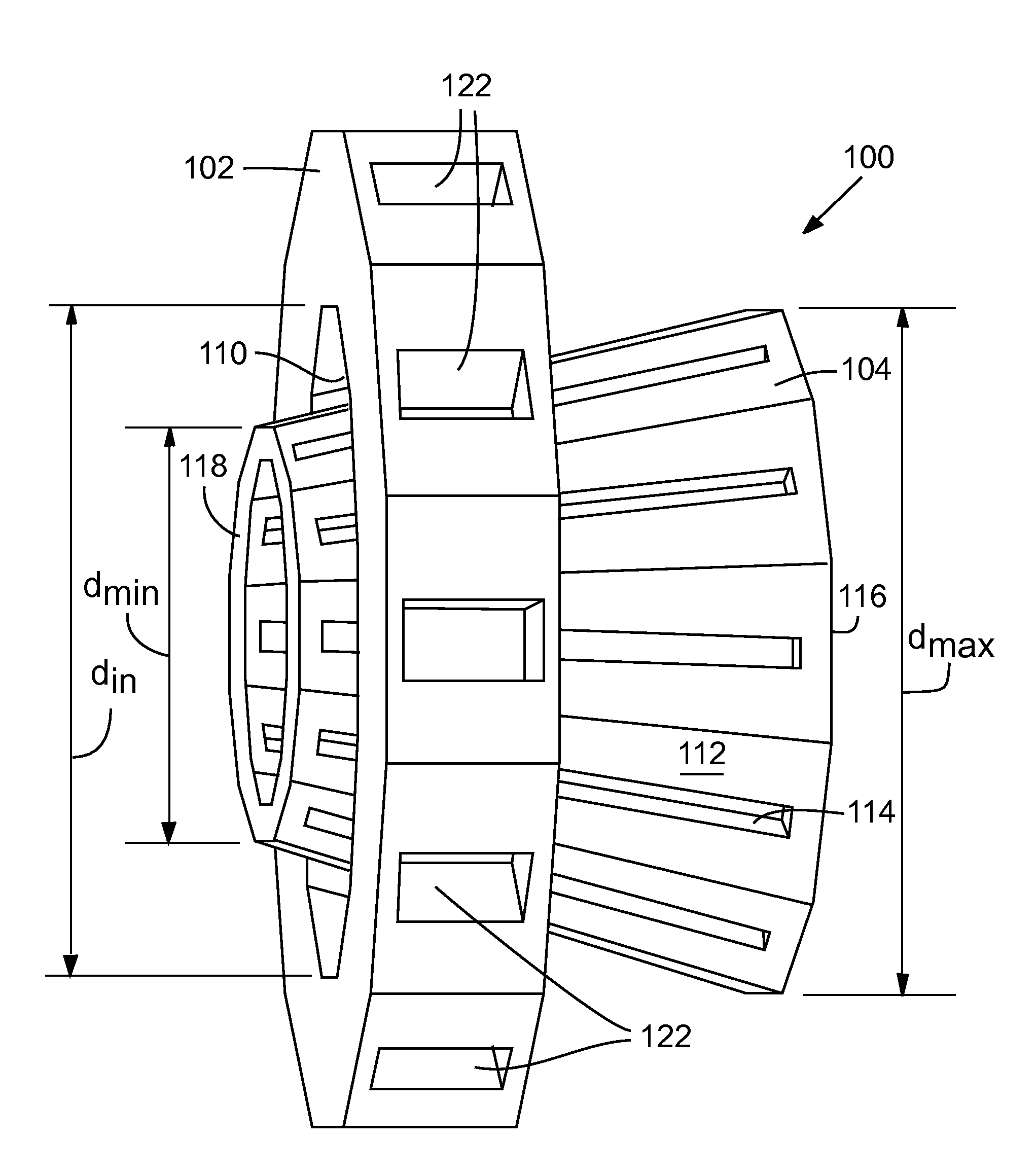
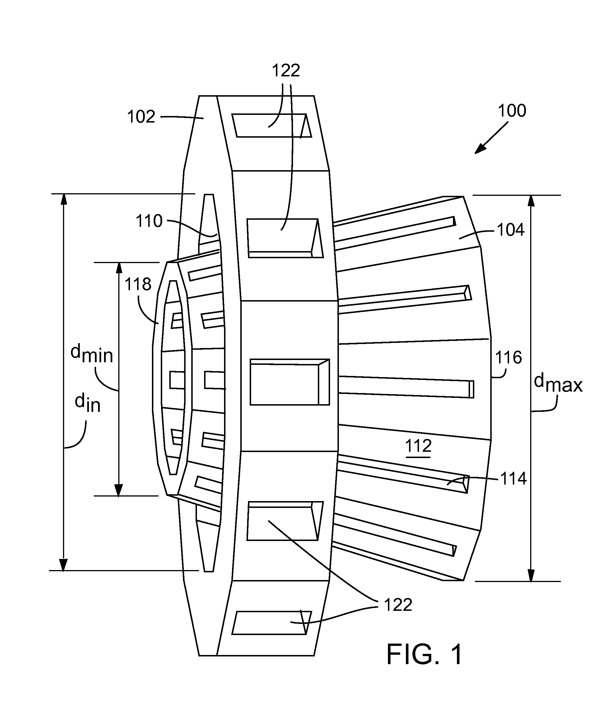
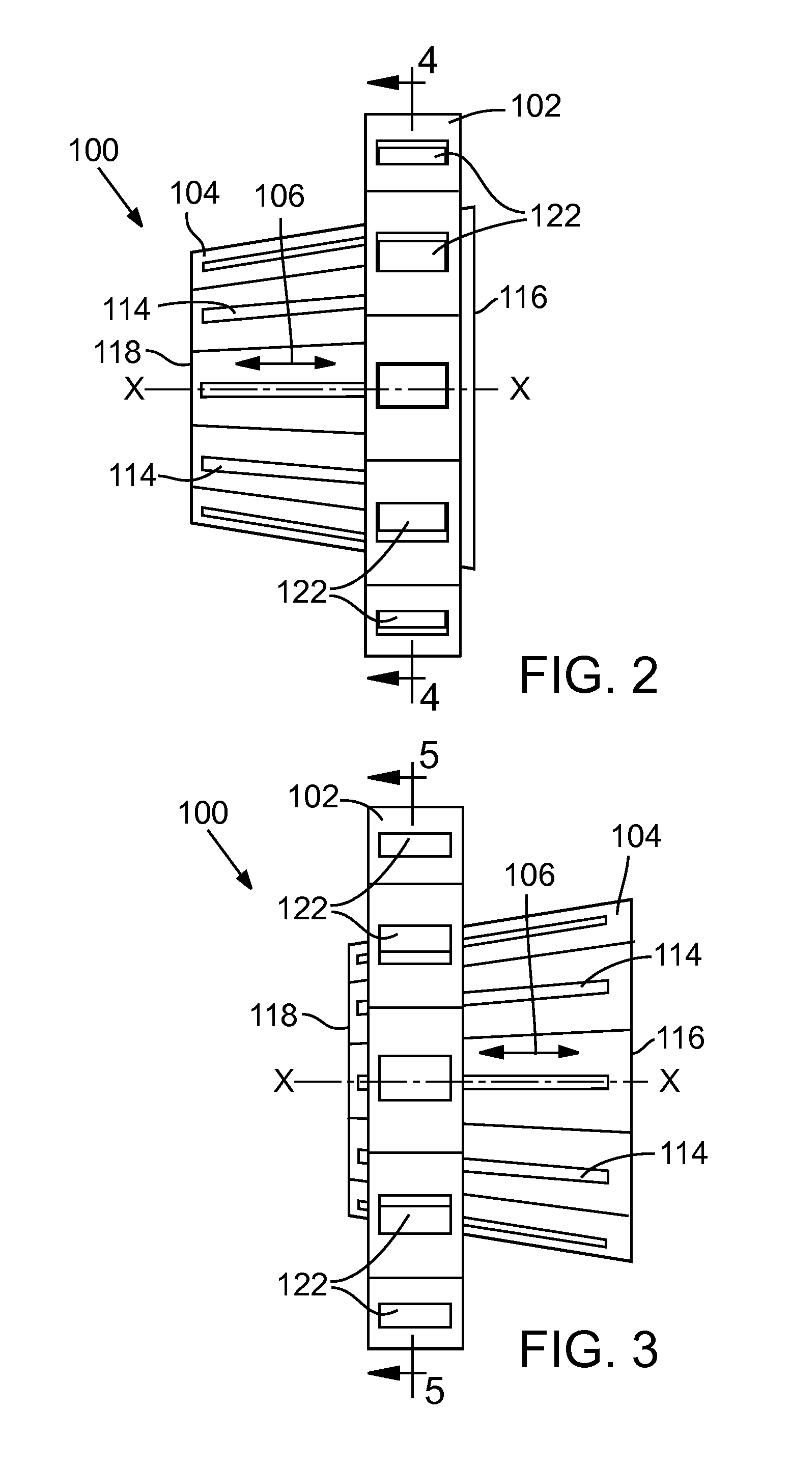
Embodiments of crimping devices for crimping stented prosthetic valves and other medical devices from a larger, expanded diameter to a smaller, crimped diameter are disclosed. Some crimping devices utilize a conical surface extending out-of-plane from the direction of crimping, where motion of the conical surface in the out-of-plane direction causes in-plane radially crimping. Other crimping devices comprise a funnel-shaped rigid body having a tapered inner lumen that compresses a medical device moving therethrough. Some funnel-shaped embodiments have slotted sides that allow portions of the medical device to project therethrough. Other funnel-shaped embodiments are used with a tubular sock to pull the medical device through the tapered lumen. Other crimping devices utilize rotating rollers that compress a medical device while the medical device spins between the rollers.

Description

CROSS REFERENCE TO RELATED APPLICATION[0001]This application claims the benefit of U.S. Provisional Patent Application No. 61 / 512,267, filed Jul. 27, 2011, which is incorporated by reference herein.FIELD[0002]The present disclosure relates to crimping devices for crimping stents, frames, stented prosthetic valves, and other medical devices from a larger, expanded diameter to a smaller, crimped diameter.BACKGROUND[0003]A stent is a generally cylindrical prosthesis introduced into a lumen of a body vessel via a catheterization technique. Stents may be self-expanding or balloon expandable. Stents are typically crimped from an initial relatively large (or expanded) diameter to a smaller, crimped diameter prior to advancement to a treatment site in the body. Before crimping, a balloon-expandable stent is typically placed over an expandable balloon on a catheter shaft. In cases where the stent was manufactured in its fully crimped diameter, the stent is often expanded and then crimped on ...

Claims


Application Information

Patent Timeline
IPC IPC(8): A61B17/00
CPCA61F2/2418A61F2/2433A61F2/958A61F2230/0067A61F2230/005A61F2230/0054A61F2230/0065A61F2002/9522A61F2/95A61F2/9522A61F2/9525
Inventor TAFT, ROBOBA, TRAVIS Z.
Owner EDWARDS LIFESCIENCES CORP
Learn More