Device And Method For Machining An Electrical Cable

a technology of electrical cables and machining methods, which is applied in the direction of turning apparatus, cable installation apparatus, electrical apparatus, etc., can solve the problems of unsatisfactory cable joint quality, unsatisfactory described conventional method of stripping electrical cables, etc., and achieve the effect of improving the quality of cable joints

Inactive Publication Date: 2013-02-07
NKT HV CABLES AB
View PDF6 Cites 8 Cited by
  • Summary
  • Abstract
  • Description
  • Claims
  • Application Information

AI Technical Summary

Benefits of technology

[0008]One object of the present invention is to provide a device for machining a cable in order to achieve a soft transition bet

Problems solved by technology

Moreover, irregularities on the cone surface may lead to locally enhanced electric field strength and can also initiate an electrical breakdown.
The described conventional method for stripping an electrical cable is unsatisfacto

Method used


Image

  • Device And Method For Machining An Electrical Cable
  • Device And Method For Machining An Electrical Cable
  • Device And Method For Machining An Electrical Cable

Examples


Embodiment Construction

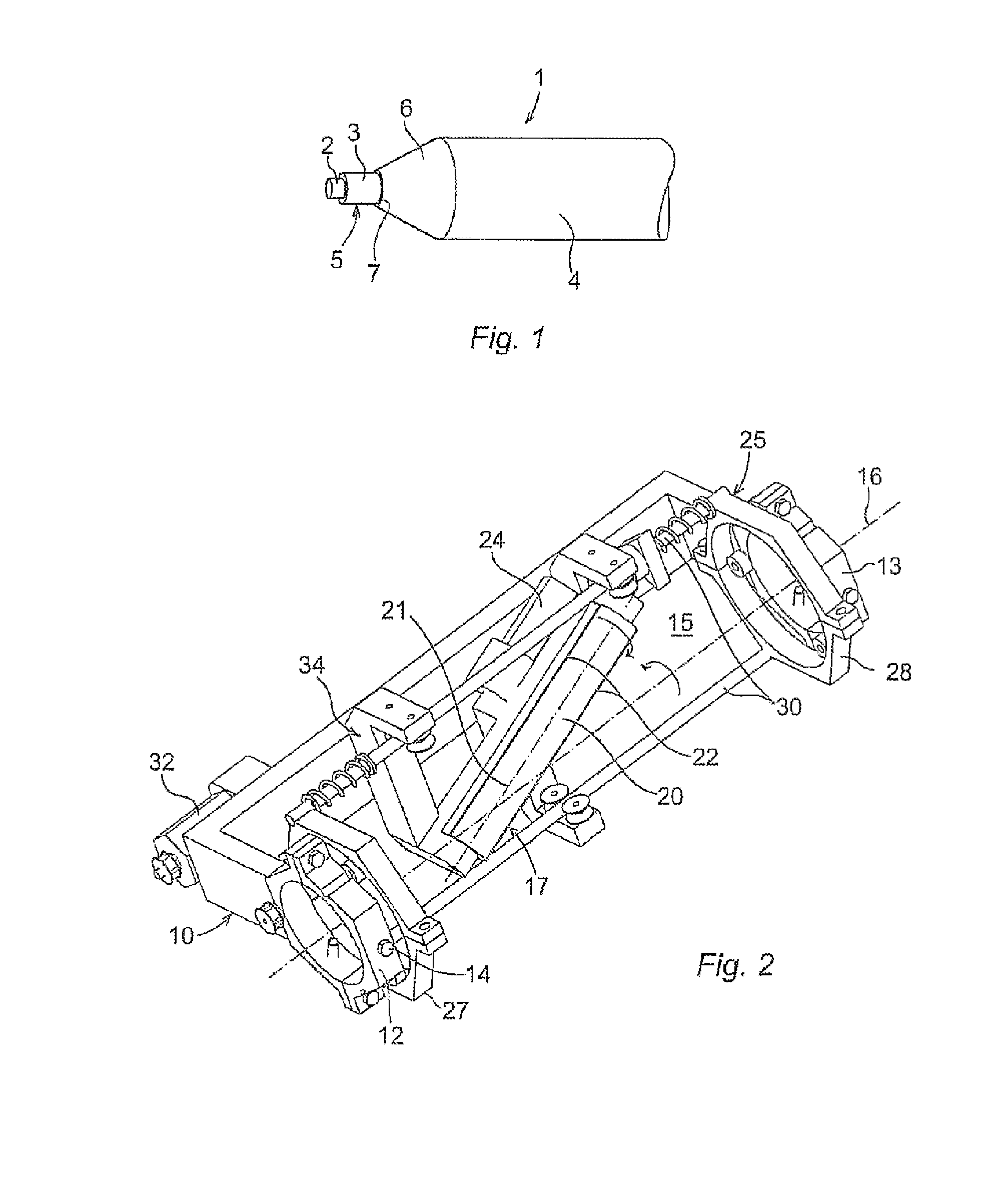
[0029]FIG. 1 shows an example of a stripped cable 1. The cable comprises a conductor 2, a conductor screen 3 surrounding the conductor, and an electrical insulation layer 4 surrounding the conductor screen 3. The conductor 2 and the conductor screen 3 form a cylindrical part 5. The insulation layer includes a conical part 6 adjoining the cylindrical part 5. The transition between cylindrical part 5 and conical part 6 includes a cone edge 7. The cone edge 7 is a part of the transition between the cone 6 and the cylindrical part 5.

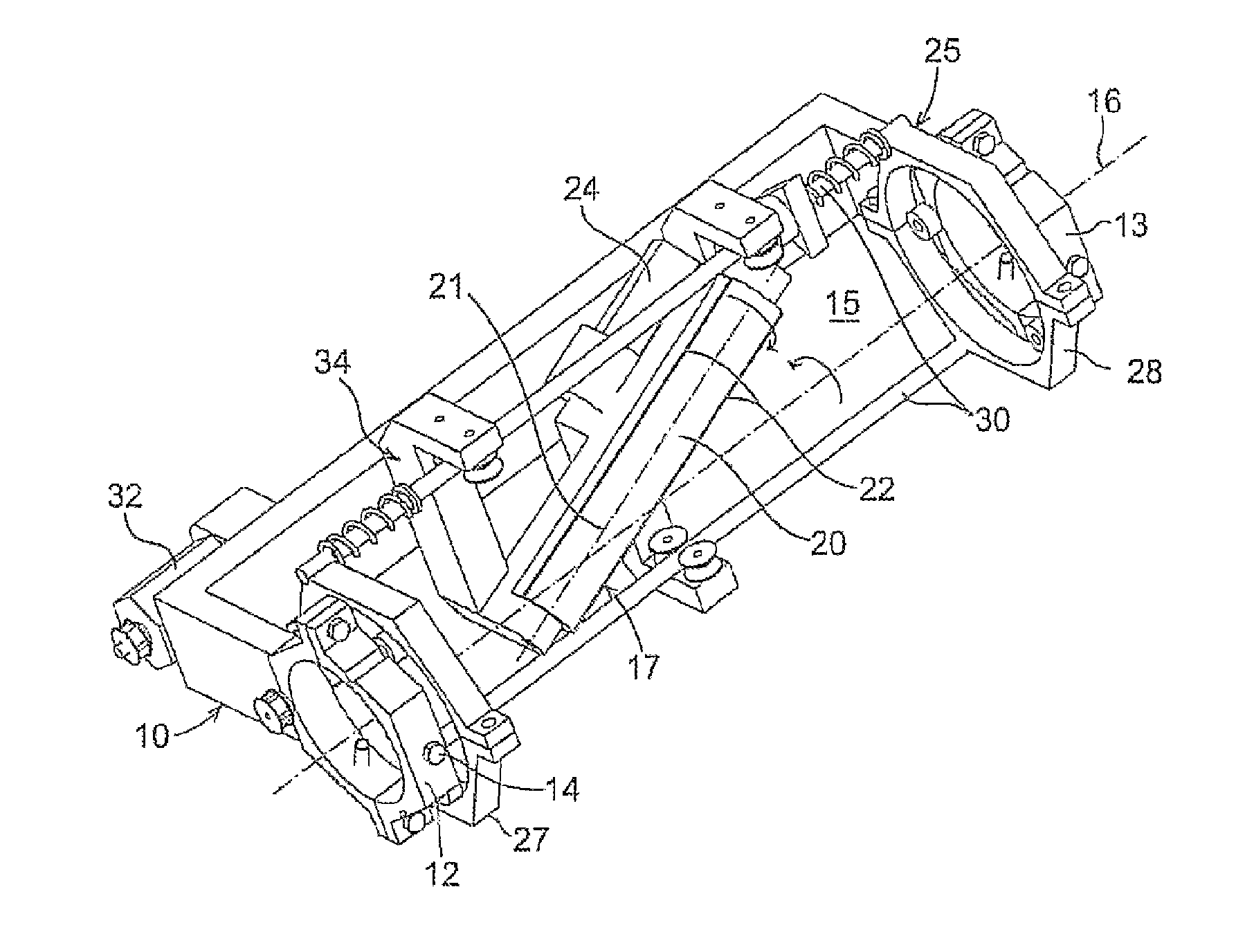
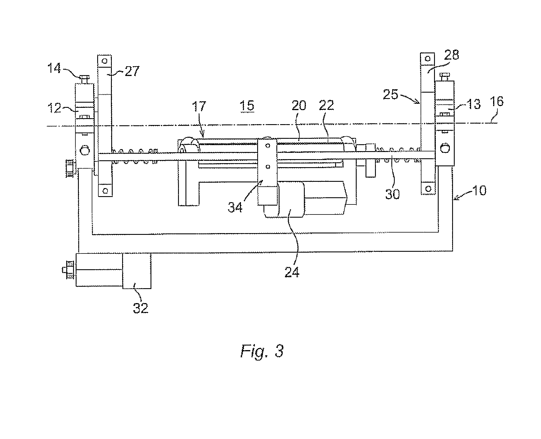
[0030]FIGS. 2-5 show a device for machining a cable 35 according to an embodiment of the invention. FIGS. 2-3 show the device without a cable and FIGS. 4-5 show the device holding a cable. The device comprises a fixture 10 arranged to receive the cable and to hold the cable in a fixed position. The fixture includes a first and a second holding element 12, 13 arranged at a distance from each other and adapted to receive the cable and to hold the cable in a fi...


PUM

PropertyMeasurementUnit
Lengthaaaaaaaaaa
Angleaaaaaaaaaa
Angleaaaaaaaaaa

Abstract

A device for machining an electrical cable having a cylindrical part and a conical part adjoining the cylindrical part. The device includes a fixture arranged to receive the cable and to hold the cable in a fixed position, the fixture defines an elongated space for accommodating the cable, a tool for removing material from the cable including at least one cutter, and rotational guiding means for guiding a first rotation of the cutter about a longitudinal axis of the space. The cutter is elongated and the longitudinal axis of the cutter is arranged inclined with respect to the longitudinal axis of the space so that the angle between the longitudinal axes of the cutter and the space is between 10 and 80 degrees. The device further includes drive means for providing a second rotation of the cutter about a rotational axis through the tool in order to cause the machining.

Description

FIELD OF THE INVENTION[0001]The present invention relates to a device and a method for machining an electrical cable having a cylindrical part and a conical part adjoining the cylindrical part. The invention is particularly suitable for machining high and medium voltage cables.BACKGROUND OF THE INVENTION[0002]A high or medium voltage electrical cable essentially comprises a conductor, a conductor screen surrounding the conductor and an electrical insulation layer surrounding the conductor screen. High voltage electrical cables have robust dimensions with typical outer diameters between 70 to 120 mm. When there is a need to join two cables, one way is to prepare a flexible vulcanized joint between the cable ends. The conductor ends are normally jointed by welding, after which the insulation layer is restored by melting and curing an insulation material in a pressurized mould arranged around the cable. For enabling the welding of the conductors, the cable ends have to be stripped.[000...

Claims


Application Information

Patent Timeline
IPC IPC(8): H01R43/00B23B5/00
CPCH02G1/005H02G1/1265H02G1/1285Y10T409/307616Y10T409/30644Y10T82/16442Y10T82/2566Y10T409/303808Y10T82/10
Inventor ANTONISCHKI, JORNGUSTAFSSON, KRISTIAN
Owner NKT HV CABLES AB
Why Eureka
Try Eureka