Heat exchanger

a technology of heat exchanger and heat exchanger plate, which is applied in the direction of indirect heat exchanger, laminated elements, lighting and heating apparatus, etc., can solve the problems of significant decrease in fin efficiency, and decrease in heat exchange efficiency, so as to improve heat exchange efficiency and reduce the pressure loss of exhaust gas , the effect of small siz

Inactive Publication Date: 2013-02-07
THE UNIV OF TOKYO +2
View PDF13 Cites 7 Cited by
  • Summary
  • Abstract
  • Description
  • Claims
  • Application Information

AI Technical Summary

Benefits of technology

[0010]In the heat exchanger according to the present invention configured as described above, a heat exchange medium flows in from the inlets formed at the vertically lower portions of the plurality of heat-exchange tubes and flow in the plurality of heat-exchange tubes arranged in parallel from the vertically lower portions to the vertically upper portions, and flows out from the outlets formed at the vertically upper portions of the plurality of heat-exchange tubes. Meanwhile, exhaust gas flows in from the inlet formed at the vertically upper portion of the shell, flows in the flow path formed between the shell and the plurality of heat-exchange tubes, and flows out from the outlet formed at the vertically lower portion of the shell. In the flow path formed between the shell and the plurality of heat-exchange tubes, the exhaust gas flows in the spaces between the plurality of heat-exchange tubes while meandering downward from the vertically upper portion via the meandering guiding section formed in either or both of the plurality of heat-exchange tubes and the shell. Accordingly, the heat exchange medium flows from the vertically lower portions to the vertically upper portions, while the exhaust gas flows from the vertically upper portion to the vertically lower portion as a whole although the exhaust gas is made to meander by the meandering guiding section, and thus, the heat exchange medium and the exhaust gas have flows opposed to each other, enhancing the heat exchange efficiency. As a result of heat exchange with the exhaust gas, condensed water is generated on flat surfaces of the plurality of heat-exchange tubes, however, the plurality of heat-exchange tubes are arranged in parallel in such a manner that each of the respective longitudinal directions thereof is mainly the vertical direction, and thus, the condensed water is collected toward the vertically lower portions and discharged. Consequently, the generated condensed water can be prevented from remaining and hindering the flow of the exhaust gas, and thus, the pressure loss of the exhaust gas can be reduced. Furthermore, since the heat exchanger according to the present invention is configured as a finless heat exchanger, the discharge of condensed water can be accelerated compared to those with fins attached between the plurality of heat-exchange tubes. Consequently, a heat exchanger having a small size and good heat exchange efficiency can be provided.
[0011]In the heat exchanger according to the present invention, the plurality of heat-exchange tubes can each include a vertical groove at a substantial center of a flat surface thereof. Consequently, condensed water generated on the flat surfaces of the plurality of heat-exchange tubes flows along the grooves to the vertically lower portions, enabling enhancement of the condensed water discharge performance, and thus, a heat exchanger having a small size and good heat exchange efficiency can be provided. Furthermore, as a result of formation of the grooves, the strength of the plurality of heat-exchanges can be enhanced. Consequently, the plurality of heat-exchange tubes can be formed using a thinner metal plate material. In such case, the groove in each of the plurality of heat-exchange tubes can be fixed by bonding inside the heat-exchange tube. Consequently, the strength of the plurality of heat-exchange tubes can further be enhanced.
[0012]In the heat exchanger according to the present invention, the meandering guiding section can include a guide wall formed inside the shell so that the exhaust gas flows in a substantially horizontal direction orthogonal to the plurality of heat-exchange tubes. In this case, the meandering guiding section can further include a rib formed toward the guide wall at a flat surface of each of the plurality of heat-exchange tubes at a position aligned with the guide wall of the shell, in addition to the guide wall. Consequently, the exhaust gas can be made to more reliably flow in the spaces between the plurality of heat-exchange tubes while meandering, enabling enhancement in heat exchange efficiency.
[0013]Further, in the heat exchanger according to the present invention, the meandering guiding section can include a plurality of ribs formed at a plurality of positions in a substantially horizontal direction on a flat surface of each of the...

Problems solved by technology

Although a heat exchanger is downsized by flattening the tubes and reducing the spaces between the tubes to enhance the efficiency of heat exchange with exhaust gas, if the spaces between the tubes are reduced, the condensed water remains between the tubes, hindering the flow of the exh...

Method used


Image

  • Heat exchanger
  • Heat exchanger
  • Heat exchanger

Examples


Embodiment Construction

[0026]One mode of carrying out the invention is discussed below as a preferred embodiment.

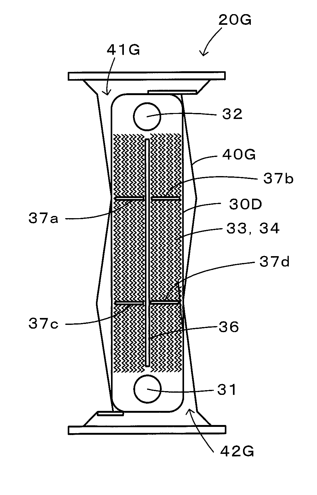
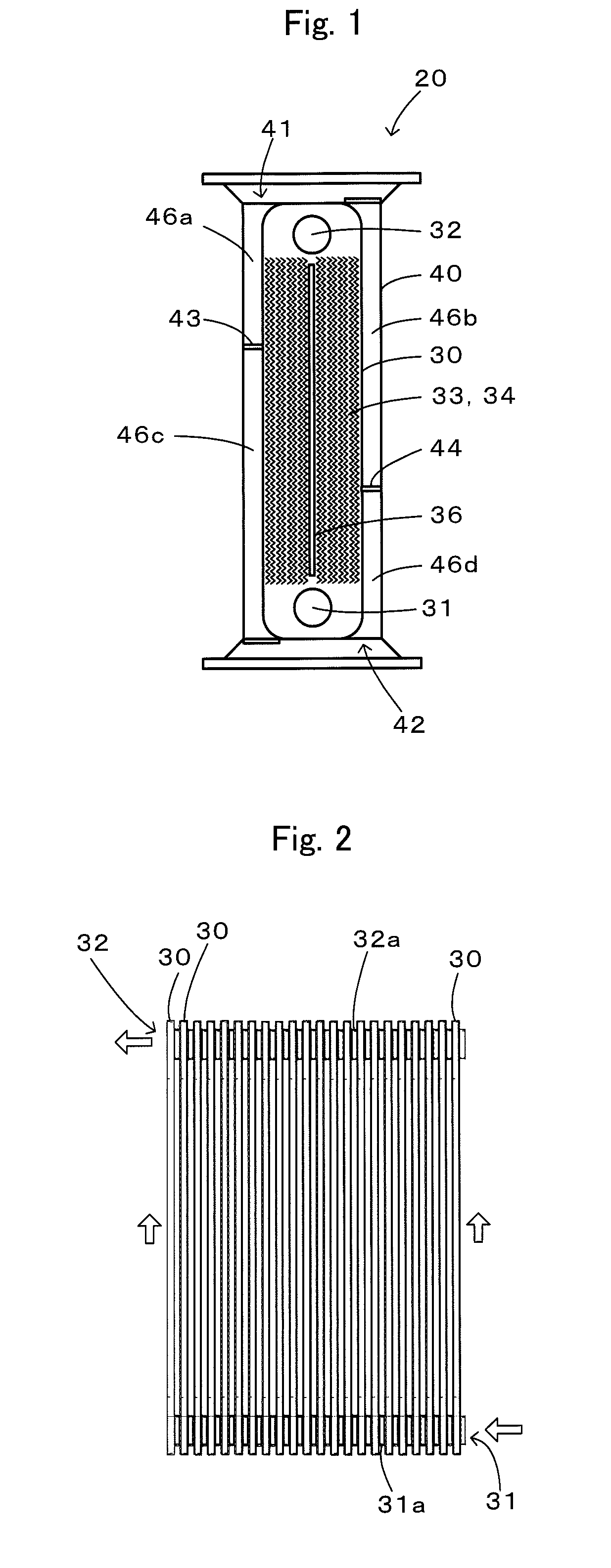
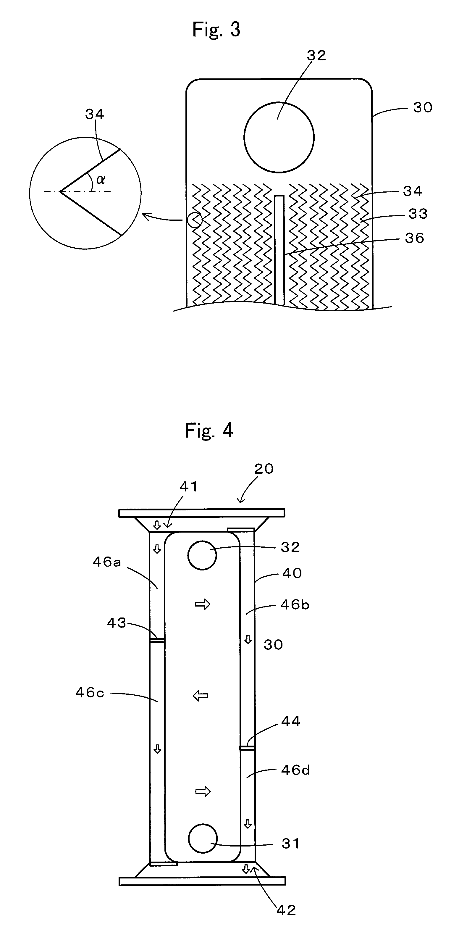
[0027]FIG. 1 is a configuration diagram illustrating a schematic configuration of a heat exchanger 20, which is an embodiment of the present invention; FIG. 2 is a side view of an outer appearance of a plurality of heat-exchange tubes 30 used in the heat exchanger 20 according to the embodiment; FIG. 3 is an enlarged diagram illustrating a heat-exchange tube 30 with a part thereof enlarged. The heat exchanger 20 according to the embodiment is configured as a finless heat exchanger that recovers heat of exhaust gas resulting from combustion via heat exchange between the exhaust gas and a heat exchange medium such as cooling water, and as illustrated, includes a plurality of (for example, 22) heat-exchange tubes 30 arranged in parallel in such a manner that each of respective longitudinal directions thereof is a vertical direction, and a shell 40 that houses the plurality of heat-exchange tubes 3...


PUM


Abstract

A plurality of heat-exchange tubes 30 each including a flat pipe including a groove 36 and wavelike depression-and-projection portions 33, 34 are arranged in parallel in such a manner that each of respective longitudinal directions thereof is a vertical direction, and a heat exchange medium is made to flow from an inlet 31 at each lower portion to an outlet 32 at each upper portion. Guide walls 43, 44 are provided in a shell 40, and exhaust gas is made to flow an inlet 41 at an upper portion to an outlet 42 at a lower portion, thereby making the exhaust gas meander in flow paths 46a to 46d and a space between the plurality of heat-exchange tubes 30. The exhaust gas and the heat exchange medium have flows opposed to each other as a whole, and a secondary flow of the exhaust gas is made to occur by the wavelike depression-and-projection portions 33, 34, thereby enhancing the heat exchange efficiency, and the arrangement in such a manner that each of the longitudinal directions is the vertical direction and the formation of a groove 36 and the wavelike depression-and-projection portions 33, 34 enable acceleration of downward discharge of condensed water.

Description

TECHNICAL FIELD[0001]The present invention relates to a heat exchanger and specifically relates to a finless heat exchanger that recovers heat of exhaust gas, which results from combustion, via heat exchange with a heat exchange medium.BACKGROUND ART[0002]Conventionally, for this type of heat exchanger, one in which cooling water is made to flow in a plurality of tubes each formed into a U-shape and exhaust gas is made to flow substantially perpendicular to the cooling water in the plurality of tubes from the side of the plurality of tubes close to outlets for the cooling water, thereby recovering heat of the exhaust gas (see, for example, non-patent literature 1). In this heat exchanger, i.e., the plurality of tubes are formed using stainless steel to prevent corrosion caused by exhaust gas, and corrugated fins are inserted between the plurality of tubes to enhance the heat exchange efficiency.CITATION LISTNon Patent Literature[0003]Non Patent Literature 1: Transactions of the Japa...

Claims


Application Information

Patent Timeline
IPC IPC(8): F28D1/053F28F13/06F28F9/02F28F1/04F28F1/06
CPCF28D7/1692F28D9/0043F28F17/005F28F3/046F28F9/22F28D21/0003
Inventor SHIKAZONO, NAOKIWAKE, TSUNEHITOIKUTA, SHIROKANDORI, ISAMUIWAMOTO, KAZUAKI
Owner THE UNIV OF TOKYO
Why Eureka
Try Eureka