Organic light emitting display device and method of manufacturing the same

a technology of light-emitting display device and which is applied in the direction of thermoelectric devices, optical elements, instruments, etc., can solve the problems of external light being disadvantageously visible to a viewer of the organic light-emitting display device, not only deterioration caused, deterioration caused by extrinsic factors, etc., to achieve the effect of reducing thickness, improving bendability, and simplifying sealing structur

Active Publication Date: 2013-02-07
LG DISPLAY CO LTD
View PDF1 Cites 26 Cited by
  • Summary
  • Abstract
  • Description
  • Claims
  • Application Information

AI Technical Summary

Benefits of technology

[0047]First, a plastic thin film having an anisotropic property is excluded in a sealing process, and sealing organic and inorganic thin films are formed on one side surface or both side surfaces of a retarder of a polarization plate, and the polarization plate is attached to a substrate on which an organic light emitting element array is formed, with an adhesive layer interposed therebetween, to encapsulate the organic light emitting element array. Since the plastic thin film having an anisotropic property is absent at an interface between the polarization plate and the substrate, external light is not visible to a viewer of the display device. That is, the sealing organic and inorganic thin films are formed to be integrated with the polarization plate, and, thus, additional plastic thin film except the sealing organic and inorganic thin films may be eliminated at an interface between the organic light emitting element array and the polarization plate. As a result, a polarization characteristic to the external light may be valid.
[0048]Second, the sealing organic and inorganic thin films are formed to be integrated with the polarization plate and, thus, additional film necessary in the encapsulation process of a related art may be

Problems solved by technology

However, the organic light emitting display device may suffer from not only deterioration caused by intrinsic factors, such as deterioration of the electrodes and light emitting layer due to oxygen and deterioration due to a reaction between the light emitting layer and an interface, but also deterioration caused by extrinsic factors such as effect of moisture, oxygen, or ultra-violet light, etc.
The

Method used


Image

  • Organic light emitting display device and method of manufacturing the same
  • Organic light emitting display device and method of manufacturing the same
  • Organic light emitting display device and method of manufacturing the same

Examples


first embodiment

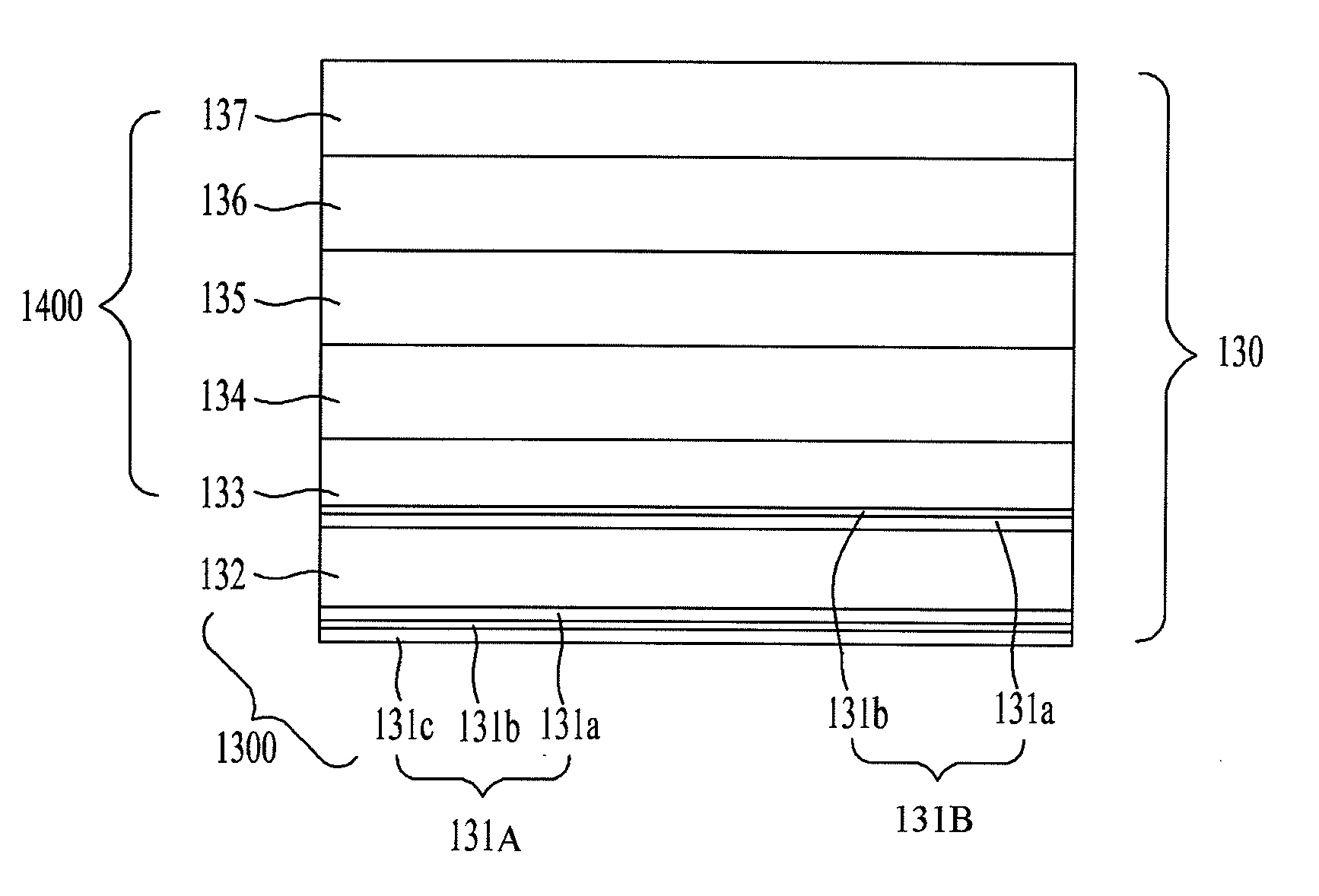
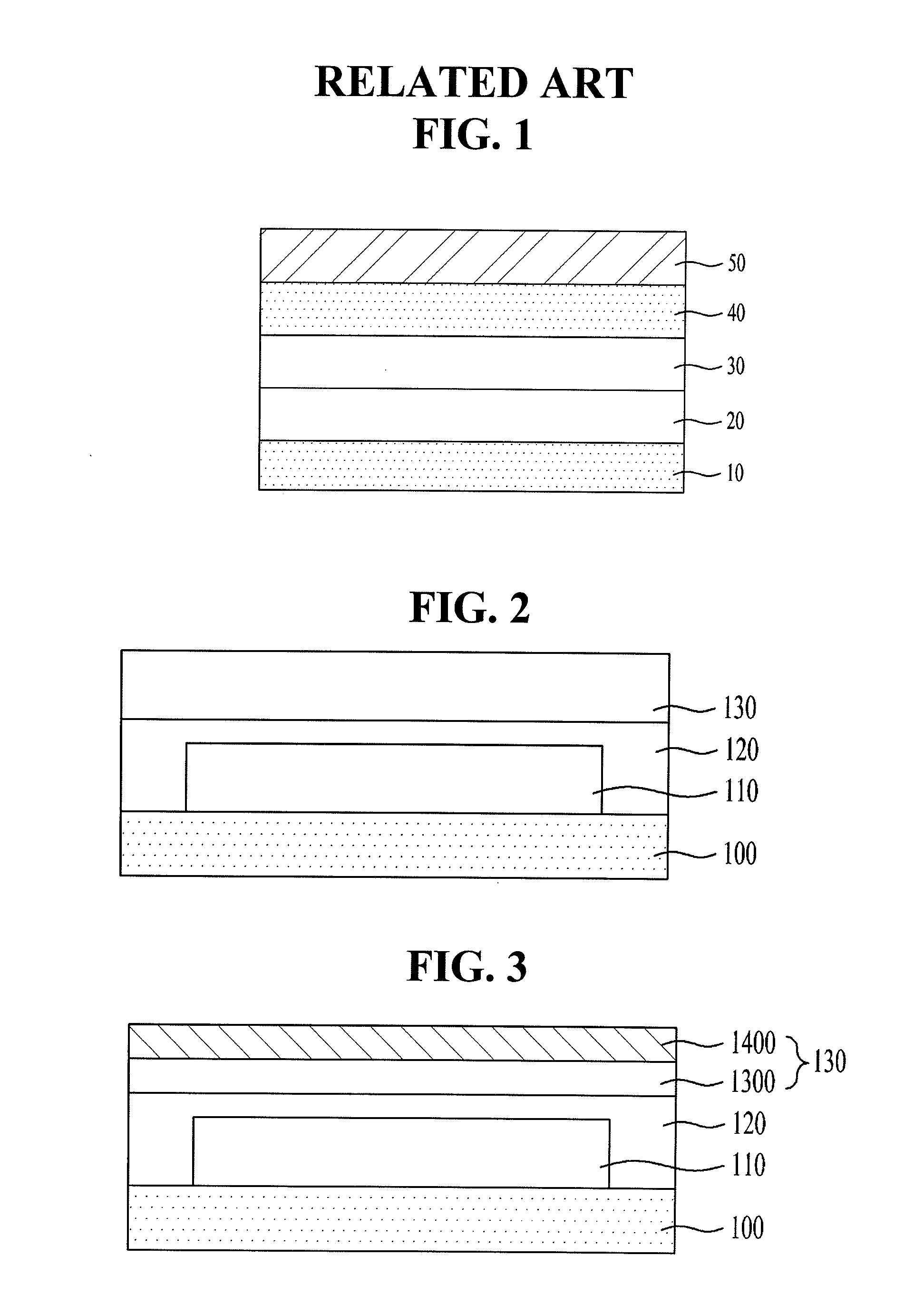
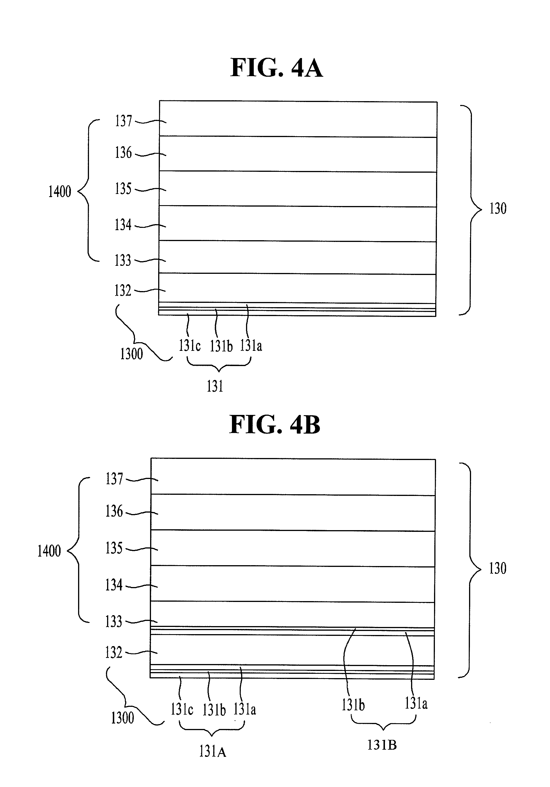
[0076]FIG. 3 is a schematic cross-sectional view of an organic light emitting display device according to the invention, FIG. 4A is a cross-sectional view of a polarization plate of FIG. 3, and FIG. 4B is a modified embodiment of FIG. 4A.

[0077]As shown in FIG. 3 and FIG. 4A, the organic light emitting display device according to the first embodiment of the invention includes a substrate 100, which may be flexible, an organic light emitting element array 110 disposed on the substrate 100, a polarization plate 130 disposed over the organic light emitting element array 110 and including a first thin-film stacked structure 131 formed of at least one organic film and at least one inorganic film, the organic film and the inorganic film being disposed one on top of the other, the first thin-film stacked structure 131 facing the organic light emitting element array 110, and an adhesive layer 120 disposed between the substrate 100 and the polarization plate 130. The first thin-film stacked s...

second embodiment

[0091]FIG. 5 is a schematic cross-sectional view of an organic light emitting display device according to the invention.

[0092]As shown in FIG. 5, the organic light emitting display device according to the second embodiment of the invention includes a substrate 100, an organic light emitting element array 110 disposed on the substrate 100, a polarization plate 2300 disposed over the organic light emitting element array 110, and an adhesive layer 120 disposed between the substrate 100 and the polarization plate 2300. The polarization plate 2300 includes a circular polarizer 230 and a first thin-film stacked structure 240 formed of at least one of an organic film 241 and an inorganic film 242. Herein, the adhesive layer 120 fully covers the organic light emitting element array 110.

[0093]As shown in FIG. 5, the polarization plate 2300 may further include a transparent optical film 250 on an outermost surface. The transparent optical film 250 may be polyethylene terephthalate (PET).

[0094...


PUM


Abstract

Discussed are an organic light emitting display device and a method of manufacturing the same in which organic and inorganic films are formed on a polarization plate, and the polarization plate is attached to an organic light emitting panel so that the organic and inorganic films seal the organic light emitting panel, thereby achieving improved polarization and a simple sealing structure.

Description

CROSS REFERENCE TO RELATED APPLICATION[0001]This application claims priority to and the benefit of Korean Patent Application No. 10-2011-0078059, filed on Aug. 5, 2011 and Korean Patent Application No. 10-2012-0050341, filed on May 11, 2012, which are hereby incorporated by reference as if fully set forth herein.BACKGROUND OF THE INVENTION[0002]1. Field of the Invention[0003]Embodiments of invention relate to an organic light emitting display device and a method of manufacturing the same, and, in particular, to an organic light emitting display device and a method of manufacturing the same in which organic and inorganic thin films are formed on a polarization plate, and the polarization plate is attached to an organic light emitting panel so that the organic and inorganic thin films seal the organic light emitting panel, thereby achieving improved polarization and a simple sealing structure.[0004]2. Discussion of the Related Art[0005]An image display device to visually provide a var...

Claims


Application Information

Patent Timeline
IPC IPC(8): H01L27/32H01L51/56
CPCG02B5/3041H01L51/5281H01L51/5256H10K50/8445H10K50/86G02B5/305H10K50/84H10K50/868
Inventor LEE, JAE-YOUNGYANG, WON-JAEKIM, MYUNG-SEOP
Owner LG DISPLAY CO LTD
Why Eureka
Try Eureka