Battery System
a battery and system technology, applied in the field of batteries, can solve the problems of detection voltage data, difficulty in processing data and cost, and large number of cells in the storage device, and achieve the effect of reducing the number of components for voltage detection of the cells and keeping the safety
- Summary
- Abstract
- Description
- Claims
- Application Information
AI Technical Summary
Benefits of technology
Problems solved by technology
Method used
Image

Examples
first embodiment
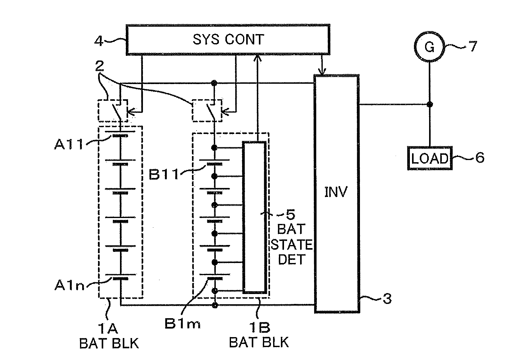
[0032]FIG. 1 shows a battery system according to the present invention. FIG. 1 is a block diagram of the battery system of the present invention. The battery system according to the present invention includes a battery block 1A including a plurality of batteries A11 to A1n connected in series and a battery block 1B including batteries B11 to B1m connected in series (m and are natural numbers more than one). The batteries A11 to A1n and B11 to B1m in each battery block may be formed with a cell or a plurality of cells connected with a series-parallel connection. The battery blocks are formed using cells having approximately homogenized characteristics by using cells manufactured in the same shape as the same model. The same cells are all used for forming the battery blocks 1A and 1B to improve easiness in assembling.
[0033]Because the battery blocks 1A and 1B are formed by connecting cells in series therein, each of the battery blocks 1A and 1B generates at both terminals a total volt...
second embodiment
[0048]FIG. 5 shows the present invention. The second embodiment is different from the first embodiment in that a battery protection circuit 8 is included in (installed integral with) the battery block 1A. In addition, the switch 2 connected to the battery block 1A is configured to be controlled by the battery protection circuit 8. FIG. 6 shows the battery protection circuit 8 in detail.
[0049]The battery protection circuit 8 includes an overvoltage protection circuit 81, an overvoltage detector 82, and a switch controller 83.
[0050]For example, the overvoltage protection circuit 81 includes Zener diodes 8A, each of which cathode is connected to a positive terminal of corresponding one of the batteries A11 to A1n and each of which anode is connected to the negative terminals of the corresponding one of the batteries A11 to A1n. A breakdown voltage of the Zener diode (Zener voltage) may be selected, for example, from 4.0 to 5.0 V for the lithium ion battery. Accordingly, though there is...
fourth embodiment
[0059]FIG. 9 shows the present invention. FIG. 9 is different from FIG. 5 in that a second battery protection circuit 9 is installed which is electrically connected to both the battery blocks 1A and 1B. FIG. 10 is a circuit diagram of the second battery protection circuit 9.
[0060]In FIG. 10, the second battery protection circuit 9 has a diode array 91 including a plurality of Zener diodes 9A which is connected in series with such a zigzag connection that one of the terminals of the batteries A11 to A1n of the battery block A1 is connected through one of the Zener diodes 9A to one of the terminals of the batteries B11 to B1m of the battery block B1 which is connected to the next one of the terminals of the batteries A11 to A1n of the battery block A1 higher potential than the former one terminal, this connection being repeated to have a voltage potential increasing order at each of connected terminals with reference to a reference potential at a parallel connection between both the b...
PUM
 Abstract
Description
Claims
Application Information