Non contact-power receiving/transmitting device and manufacturing method therefor

a technology of non-contact power and receiving/transmitting device, which is applied in the direction of rail devices, magnets, magnetic bodies, etc., can solve the problems of reducing the size of the shield as much, failure of the device, etc., and achieves the effect of increasing the size of the shield and suppressing the decrease in the transmission efficiency of electric power

Inactive Publication Date: 2013-02-14
TOYOTA JIDOSHA KK
View PDF1 Cites 35 Cited by
  • Summary
  • Abstract
  • Description
  • Claims
  • Application Information

AI Technical Summary

Benefits of technology

[0014]The invention provides a non-contact power receiving / transmitting device that suppresses a decrease in transmission efficiency of electric power and an increase in size of a shield in non-contact reception or non-contact transmission of electric power using a resonance method, and a manufacturing method for the non-contact power receiving / transmitting device.
[0026]According to the aspects of the invention, it is possible to provide a non-contact power receiving device that is used to receive electric power in a non-contact manner using a resonance method or a non-contact power transmitting device that is used to transmit electric power in a non-contact manner using a resonance The non-contact power receiving device and the non-contact power transmitting device according to the aspects of the invention are able to suppress a decrease in transmission efficiency of electric power and an increase in size of a shield.

Problems solved by technology

The electromagnetic field generated around a coil unit including self-resonance coils may function as an electromagnetic noise for another electrical device, or the like, and, for example, it may be cause a noise of a radio, or the like.
In addition, when a conductor is placed in the electromagnetic field, the conductor may be heated by electromagnetic induction caused by the electromagnetic field, so an increase in temperature may cause a failure of a device.
In addition, when electric power is supplied using the resonance method, it may be necessary to reduce the size of the shield as much as possible in terms of mounting space of a vehicle.

Method used


Image

  • Non contact-power receiving/transmitting device and manufacturing method therefor
  • Non contact-power receiving/transmitting device and manufacturing method therefor
  • Non contact-power receiving/transmitting device and manufacturing method therefor

Examples


Embodiment Construction

[0041]Hereinafter, an embodiment of the invention will be described in detail with reference to the accompanying drawings. Note that like reference numerals denote the same or corresponding components and the description thereof is not repeated.

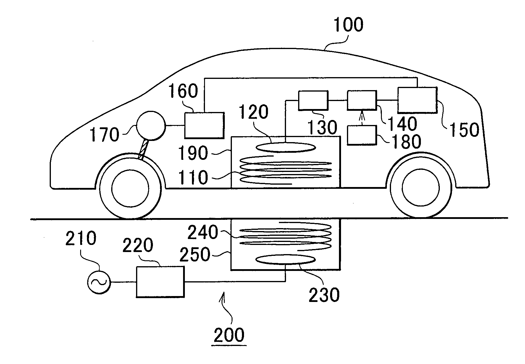
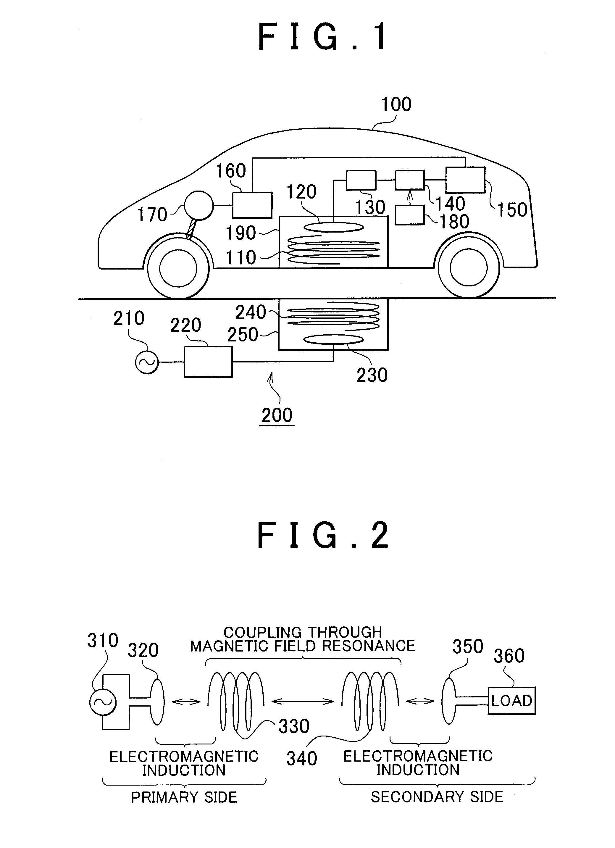
[0042]FIG. 1 is an overall configuration diagram of a non-contact power supply system that has a non-contact power receiving device according to the embodiment of the invention. As shown in FIG. 1, the non-contact power supply system includes a vehicle 100 and a power supply device 200. The vehicle 100 includes a secondary self-resonance coil 110, a secondary coil 120, a rectifier 130, a DC / DC converter 140, an electrical storage device 150 and a coil case 190. In addition, the vehicle 100 further includes a power control unit (hereinafter, also referred to as PCU) 160, a motor 170 and a vehicle electronic control unit (ECU) 180. The secondary self-resonance coil 110, the secondary coil 120 and the coil case 190 constitute the non-contact pow...


PUM

PropertyMeasurementUnit
frequencyaaaaaaaaaa
frequencyaaaaaaaaaa
frequencyaaaaaaaaaa

Abstract

A manufacturing method for a non-contact power receiving / transmitting device that transmits or receives electric power in a non-contact manner and that includes a coil unit and an electromagnetic shield, wherein the coil unit includes a self-resonance coil that is configured to receive or transmit electric power via an electromagnetic field generated through electromagnetic resonance and an adjusting unit that adjusts a resonance frequency of the self-resonance coil, the manufacturing method including: installing the coil unit; arranging the electromagnetic shield around the self-resonance coil except a direction in which electric power is received or transmitted; and adjusting the adjusting unit in accordance with a distance between the coil unit and a surface of the electromagnetic shield vertical to a direction of the electromagnetic field inside the self-resonance coil so that the resonance frequency becomes a predetermined frequency.

Description

BACKGROUND OF THE INVENTION[0001]1. Field of the Invention[0002]The invention relates to a non-contact power receiving / transmitting device and a manufacturing method therefor and, more particularly, to a non-contact power receiving / transmitting device of which the resonance frequency is adjustable by a resonance method and a manufacturing method therefor.[0003]2. Description of the Related Art[0004]In recent years, as an environmentally friendly vehicle, a vehicle that is equipped with an electrical storage device (for example, a secondary battery, a capacitor, or the like) and that is propelled by driving force generated from electric power stored in the electrical storage device becomes a focus of attention. Such a vehicle, for example, includes an electric vehicle, a hybrid vehicle, a fuel cell electric vehicle, and the like.[0005]There is known a hybrid vehicle that is able to charge an in-vehicle electrical storage device from a power supply outside the vehicle as in the case o...

Claims


Application Information

Patent Timeline
Patent Type & Authority Applications(United States)
IPC IPC(8): H01F38/14H01F41/00B60L5/00B60M7/00H02J7/00
CPCB60L11/182H01F27/36H01F38/14H02J5/005Y10T29/4902Y02T10/7005Y02T90/122Y02T90/14H02J7/025Y02T10/7072H02J50/12B60L53/126Y02T10/70H02J50/70H01F27/363Y02T90/12
Inventor ICHIKAWA, SHINJI
Owner TOYOTA JIDOSHA KK
Why Eureka
Try Eureka