
Phased-array synthetic aperture sonar system

a synthetic aperture and phasedarray technology, applied in the field of phasedarray synthetic aperture sonar system, can solve the problem of rare sampling, and achieve the effect of increasing the accuracy of the sonar image and maintaining the processing speed

Inactive Publication Date: 2013-02-14
HITACHI INFORMATION & CONTROL SOLUTIONS LTD +1
View PDF4 Cites 4 Cited by
  • Summary
  • Abstract
  • Description
  • Claims
  • Application Information

AI Technical Summary

Benefits of technology

The patent aims to improve the accuracy of sonar images while maintaining a reasonable processing speed. This means that the technology can produce more accurate sonar images without sacrificing the speed at which the data is processed.

Problems solved by technology

In addition, it is rare to perform sampling at a time of the sound propagation delay Tdi.

Method used


Image

  • Phased-array synthetic aperture sonar system
  • Phased-array synthetic aperture sonar system
  • Phased-array synthetic aperture sonar system

Examples


Embodiment Construction

[0076]The following details an embodiment of the present invention (referred to as an “embodiment”) by referring to appropriate drawings.

>

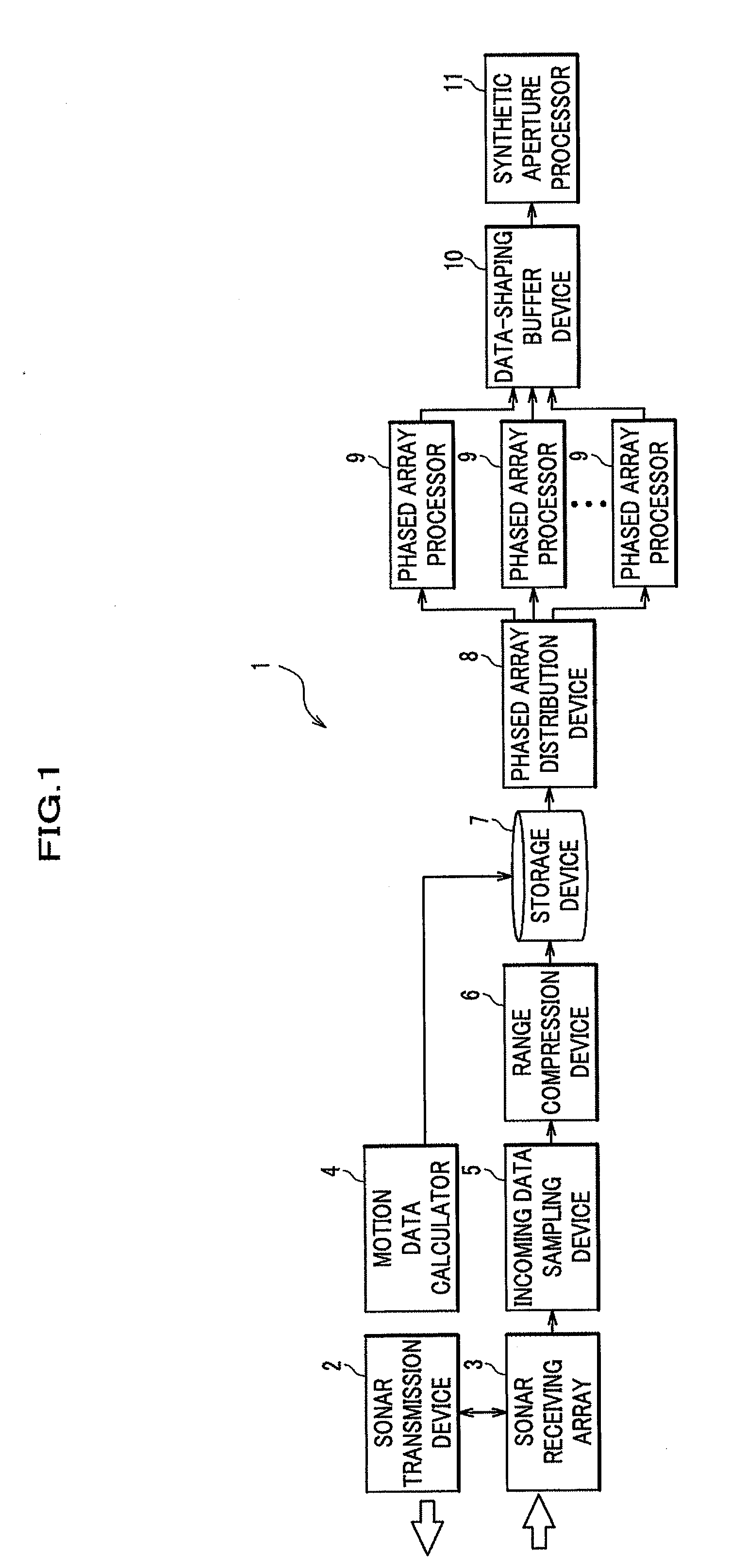
[0077]FIG. 1 illustrates, as an example, how to configure a phased-array synthetic-aperture sonar system according to an embodiment of the present invention.

[0078]A phased-array synthetic-aperture sonar system 1 includes a sonar transmission device 2, a sonar receiving array 3, a motion data calculator 4, an incoming data sampling device 5, a range compression device 6, a storage device 7, a phased array distribution device 8, a plurality of phased array processors 9, a data-shaping buffer device 10, and a synthetic aperture processor 11.

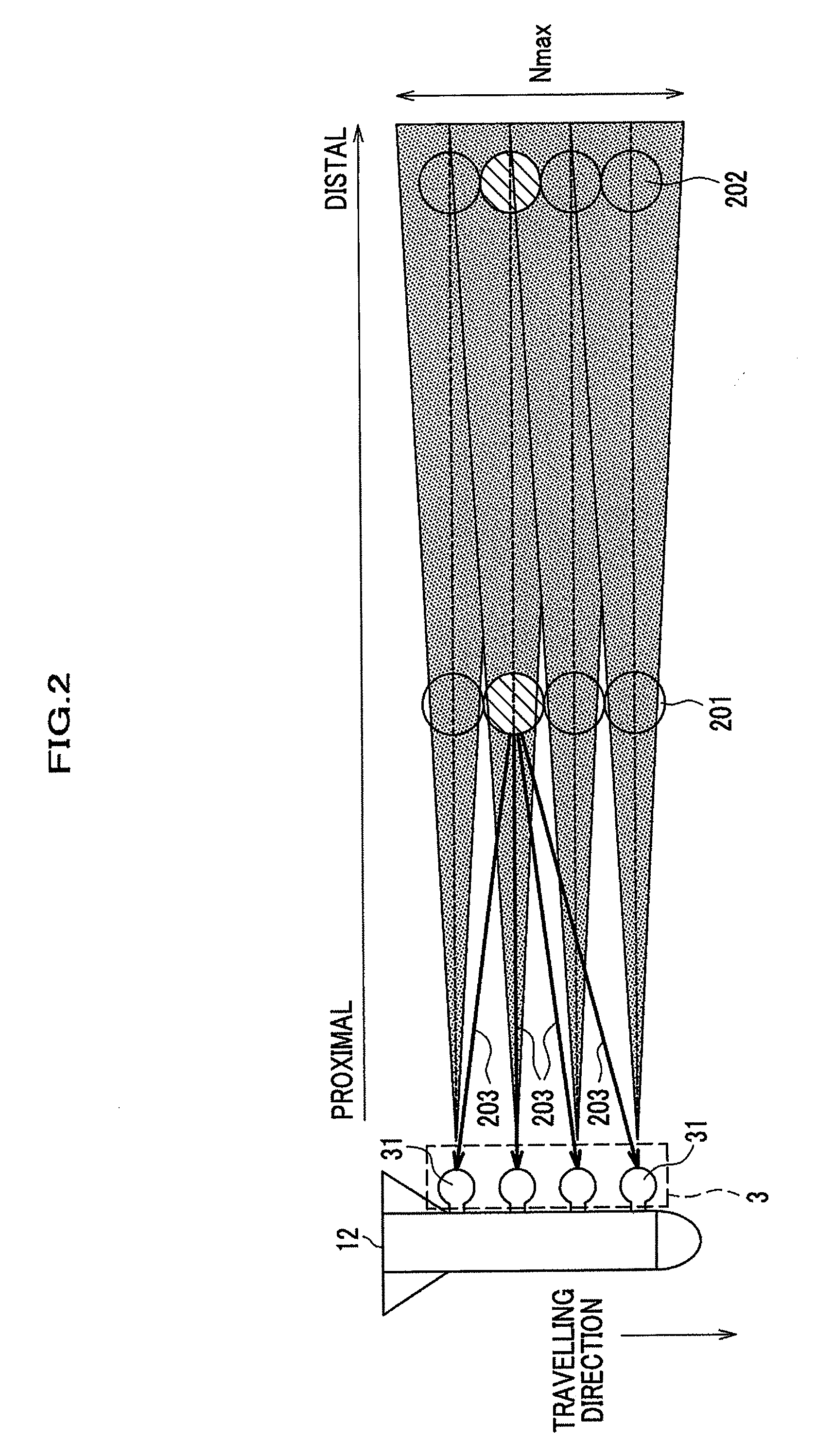
[0079]The sonar transmission device 2 transmits a pulse (sound wave), and a platform 12 (FIG. 2) has one sonar transmission device 2.

[0080]The sonar receiving array 3 has a plurality of sonar receivers 31 (FIG. 2), which are arranged with an interval at ½ wavelength of a pulse. The number of lines for the sonar re...


PUM


Abstract

It is an object to maintain a processing speed while increasing accuracy of a sonar image. Disclosed is a phased-array synthetic-aperture sonar system, including: a plurality of phased array processors (9) which perform, in parallel, phased array processing for a plurality of incoming data; a phased array distribution device (8) which distributes each simultaneously incoming data to the plurality of phased array processors (9), the incoming data being input from a plurality of receivers disposed in a platform; a synthetic aperture processor (11) which performs synthetic aperture processing by using a plurality of phased array processing results; and a data-shaping buffer device (10) which transfers the phased array processing results output from the plurality of phased array processors (9) to the synthetic aperture processor (11) in the order of receipt of the incoming data.

Description

TECHNICAL FIELD[0001]The present invention relates to techniques for a phased-array synthetic-aperture sonar system.BACKGROUND ART[0002]A process of conventional synthetic aperture sonar, for example, includes: using a 1-CH (channel) transmitter and receiver included in sonar; recording echo (reflected sound wave) data as obtained from a seabed when using a single pulse (1 ping); and repeating data recording while moving a platform such as an underwater probe. Then, a plurality of the recorded echo data are synthesized by synthetic aperture processing to yield a given synthetic aperture sonar image.[0003]FIGS. 8 to 10 describe conventional synthetic aperture sonar. In FIGS. 8 and 9, similar elements have the same reference signs so as to avoid description redundancy.[0004]First, FIG. 8 illustrates that a platform 12 has a 1-CH (single) receiver 31. A transmitter (not shown) transmits a sound wave. FIG. 8 illustrates that while spreading in an azimuth direction, which is a travelling...

Claims


Application Information

Patent Timeline
IPC IPC(8): G01S15/89
CPCG01S15/8904
Inventor GOTO, JINEBINA, TOMOHITOSAWA, TAKAO
Owner HITACHI INFORMATION & CONTROL SOLUTIONS LTD
Learn More