Electrodynamic sound-emitting device

a sound-emitting device and electrodynamic technology, applied in the direction of transducer diaphragms, loudspeaker diaphragm shapes, instruments, etc., can solve the problem of accidental contact of pedestrians, and achieve the effect of simple structure and environmental resistan

Inactive Publication Date: 2013-02-14
MITSUBISHI ELECTRIC CORP
View PDF7 Cites 11 Cited by
  • Summary
  • Abstract
  • Description
  • Claims
  • Application Information

AI Technical Summary

Benefits of technology

[0020]According to the present invention, an electrodynamic sound-emitting device can be provided that is light and thin, excels in...

Problems solved by technology

However, when running at low speed, the hybrid vehicles do not run powered by the combustion engine, but they are mainly in a running mode powered by the electric motor; therefore, no engine sound nor exhaust sound is generated, and furthermore, as for the electric vehicles and fuel cell vehicles, they run driven by the electric motor over the whole range of driving, which has made them extremely quiet electric moving bodies.
However, ...

Method used


Image

  • Electrodynamic sound-emitting device
  • Electrodynamic sound-emitting device
  • Electrodynamic sound-emitting device

Examples


embodiment 1

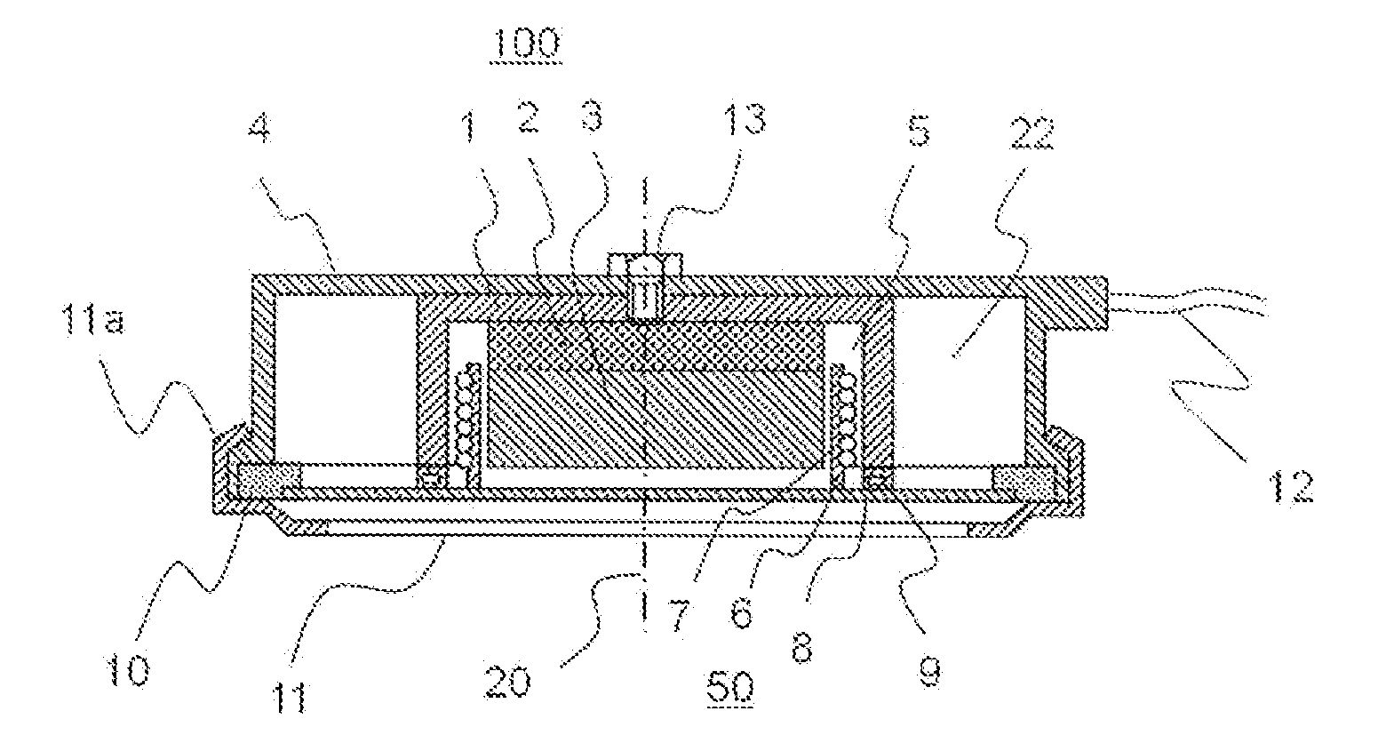
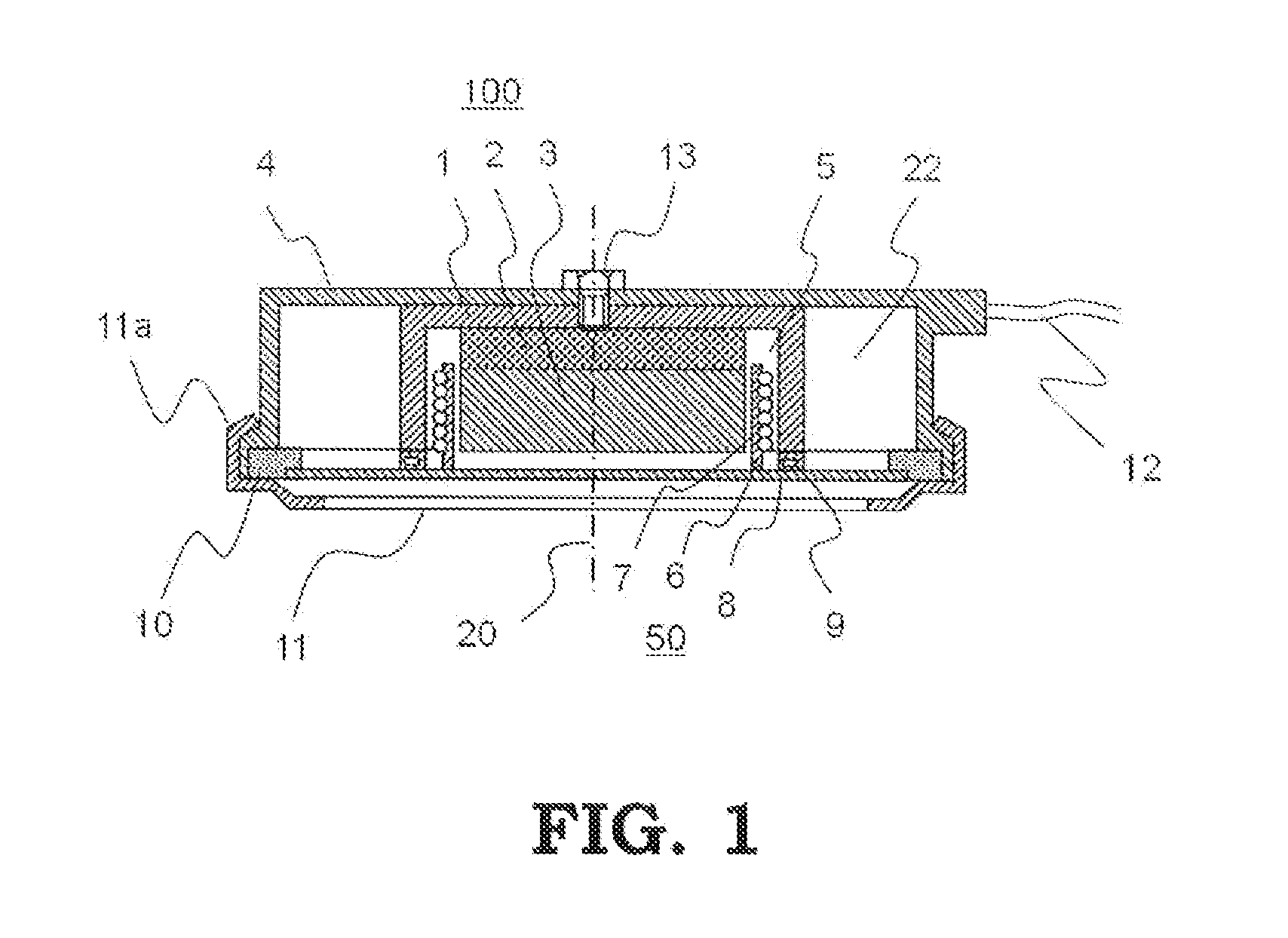
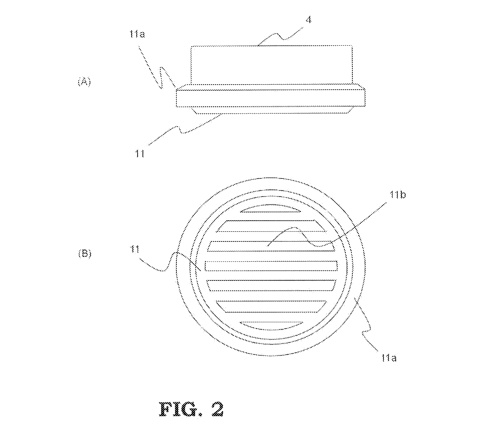
[0032]FIG. 1 is a schematic cross-sectional view showing the configuration of an electrodynamic sound-emitting device according to Embodiment 1 of the present invention. Moreover, FIG. 2 is an external view of the electrodynamic sound-emitting device shown in FIG. 1; FIG. 2(A) is a front view and FIG. 2(3) a bottom view. As shown in FIG. 2, the overall shape of this electrodynamic sound-emitting device is circular. In FIG. 1, one of the magnetic pole ends of a columnar magnet 2 is glued, coaxially with respect to an outer yoke 1, onto the inner side of the bottom of the outer yoke 1 that is made of magnetic material and formed in a shape having a bottom and cylindrical side wall. Moreover, a columnar inner yoke 3 made of magnetic material is glued onto the other magnetic pole end of the magnet 2, coaxially with respect to the outer yoke 1 and magnet 2. Those outer yoke 1, magnet 2 and inner yoke 3 constitute a magnetic circuit 100. The directions, shown by the dotted-dashed line in ...

embodiment 2

[0046]FIG. 7 is a schematic cross-sectional view showing the configuration of an electrodynamic sound-emitting device according to Embodiment 2 of the present invention; the same reference numerals as those in FIG. 1 represent the same or corresponding portions. In this Embodiment 2, a flange 8a extending in an axial direction is provided by bending, for example, along the outer circumferential edge of the diaphragm 8. The outer circumferential surface of this flange 8a and the inner circumferential surface of the annular second elastic member 10 serve as a gluing portion 10d, on which both are glued and fixed to each other. Moreover, the outer circumferential edge of the second elastic member 10 is clamped and supported by the casing 4 and the fitting portion 11a of the front cover 11.

[0047]Incidentally, the same as Embodiment 1, the second elastic member 10 is made of flexible foam rubber or flexible foam resin including large numbers of pores by the foaming processing, which ther...

embodiment 3

[0051]FIG. 9 and FIG. 10 each are a schematic cross-sectional view showing the configuration of an electrodynamic sound-emitting device according to Embodiment 3 of the present invention; in the figure, the same reference numerals as those in FIG. 1 and FIG. 7 represent the same or corresponding portions. The outer circumferential surface of the flange 8a extending in an axial direction along the outer circumferential edge of the diaphragm 8 and the inner circumferential surface of the annular second elastic member 10 serve as the gluing portion 10d, on which both are glued and fixed with each other, and furthermore the outer circumferential edge of the annular second elastic member 10 is clamped and supported by the fitting portion 11a of the casing 4 and the front cover 11.

[0052]Incidentally, the second elastic member 10, the same as Embodiments 1 and 2, is made of flexible foam rubber or flexible foam resin including large numbers of pores by the foaming processing, which is ther...


PUM


Abstract

A casing for covering an outer yoke is provided; an acoustic cavity is formed by this casing; a diaphragm and the outer surface of a side wall of the outer yoke; a second elastic member is provided to join the outer circumferential edge of the casing to the outer circumferential edge of the diaphragm without any gap therebetween; this second elastic member includes pores formed by foaming and made of a material whose elastic modulus is smaller than that of a first elastic member; and pores communicating through from the back surface of the second elastic member, that is the inner side of the casing, to the front surface that is the opposite side of the back surface are eliminated.

Description

TECHNICAL FIELD[0001]The present invention relates to a sound-emitting device used for an alarm sound generator for informing pedestrians, etc. around an electric moving body of its approaching or presence, and in particular to an electrodynamic sound-emitting device for generating sound using an electrodynamic exciter.BACKGROUND ART[0002]Following the practical development of electric bicycles and carts in recent years, transportation means serving as various kinds of moving bodies, such as electric motorcycles and electric motor vehicles, have begun to be rapidly powered by electricity. Specifically, as the replacement of motor vehicles powered by an internal combustion engine, there have been developed one after another vehicles such as hybrid vehicles powered by both gasoline engine and electric motor, electric vehicles powered by an electric motor driven by an onboard battery that is charged by a household-use power source or by a battery charger installed at gas stations or po...

Claims


Application Information

Patent Timeline
IPC IPC(8): H04R1/02
CPCG10K9/13H04R1/023H04R1/025H04R1/2811H04R7/06H04R7/20H04R2499/13H04R31/006H04R2207/021H04R2231/003H04R2307/025H04R2307/201H04R2307/207H04R9/06
Inventor INOUE, SATORUSEKIYA, MUTSUOSUZUKI, SEIKI
Owner MITSUBISHI ELECTRIC CORP
Why Eureka
Try Eureka