Vehicle speed, fuel, and revenue optimizer

a technology of vehicle speed and fuel, applied in the field of vehicles, can solve problems such as beginning to decline, and achieve the effects of reducing the overall operating cost, minimizing negative effects, and optimizing resource utilization

Inactive Publication Date: 2013-02-14
SMITH DAVID B +1
View PDF3 Cites 28 Cited by
  • Summary
  • Abstract
  • Description
  • Claims
  • Application Information

AI Technical Summary

Benefits of technology

[0026]This invention broadly resides in apparatus and methods to sense powered vehicle operating conditions, and compute and display to the operator the instant, most advantageous or optimum speed for conditions based on variable and fixed costs for that particular vehicle. Instead of the conventional or traditional display of fuel consumption relative to distance, the invention computes and displays the speed at w

Problems solved by technology

Since fuel costs and certain other costs increase as vehicle speed increases, the net revenue in dollars per hour as a function

Method used


Image

  • Vehicle speed, fuel, and revenue optimizer
  • Vehicle speed, fuel, and revenue optimizer
  • Vehicle speed, fuel, and revenue optimizer

Examples


Embodiment Construction

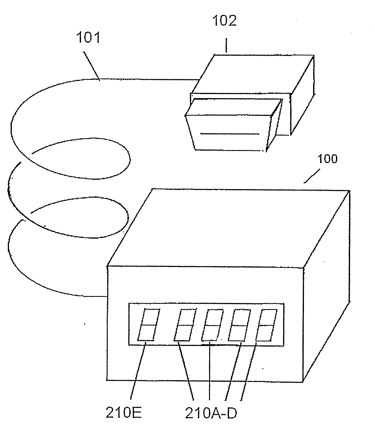
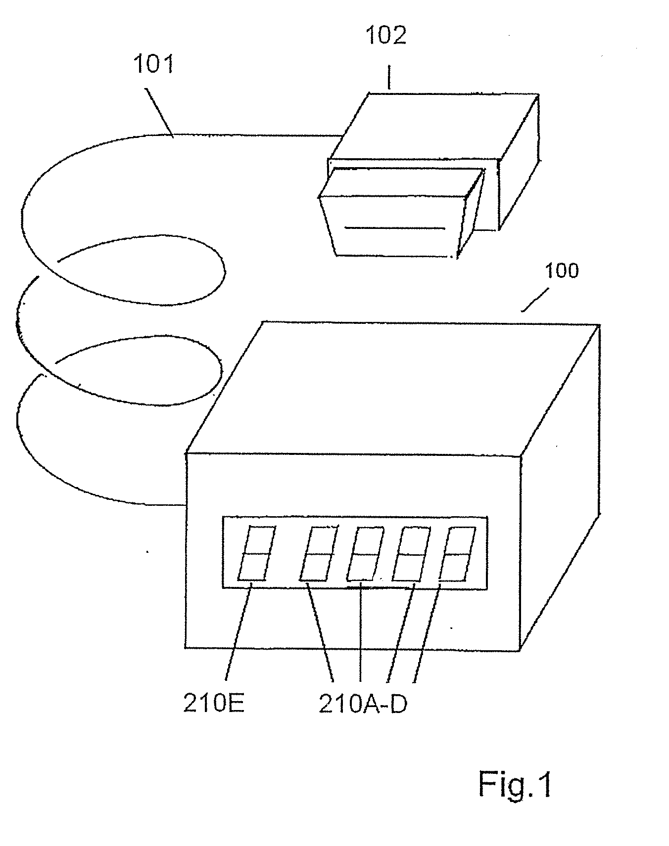
[0035]Embodiments of this invention provide improved information to guide operators of powered vehicles to operate the vehicle in ways to minimize cost, fuel consumption, waste and emissions. This invention applies to any powered vehicle traveling through a fluid including ground vehicles such as autos, trucks and trains; watercraft, and aircraft. The basic apparatus is shown in FIG. 1. Item 100 is a case or enclosure which may rest on, and be securely attached, to a dashboard, cockpit, wheelhouse, or command center of a vehicle, with the display 210 being in clear view of the operator. The housing 100 may measure approximately 4″ by 2″ by 3″, more or less.

[0036]An electrical cord 101 connects the electronics internal to the unit 100 to a data connector or data bus plug 102, configured to plug into the vehicle data bus jack or vehicle data bus receptacle typically located close to the operator station. For example, automobiles and light trucks sold in the U.S. and elsewhere since 19...


PUM


Abstract

Apparatus and methods are used to sense powered vehicle operating conditions, and compute and display to the operator the instant, most advantageous or optimum speed for conditions based on variable and fixed costs for that particular vehicle. Instead of the conventional or traditional display of fuel consumption relative to distance, the invention computes and displays the speed at which all cost factors result in optimal utilization of resources. If adhered to by the operator, either manually or through direct interface with vehicle speed control, this speed will provide the best balance between distance traveled per unit time with minimum negative impact from fixed and operating costs, resulting in minimum overall operating cost as well as maximum profit potential for the commercial operator. In addition, waste of valuable and limited-supply fossil fuel is minimized by encouraging avoidance of excessive speeds that waste fuel.

Description

REFERENCE TO RELATED APPLICATION[0001]This application is a continuation-in-part of U.S. patent application Ser. No. 13 / 552,203, filed Jul. 18, 2012, which claims priority from U.S. Provisional Patent Application Ser. No. 61 / 572,575, filed Jul. 18, 2011, the entire content of both of which is incorporated herein by reference.FIELD OF THE INVENTION[0002]This invention broadly resides in apparatus and methods to sense powered vehicle operating conditions, and, in particular, to apparatus and methods to compute and display the most advantageous or optimum speed based on variable and fixed costs for that particular vehicle.BACKGROUND OF THE INVENTION[0003]Since the inception of powered vehicles, there has been a desire to reduce cost of operation, fossil fuel or other energy consumption, as well as emissions of pollutants and greenhouse gases from automobiles, buses, trucks, trains, boats and aircraft powered by internal or external combustion engines (ICE and ECE) and other prime mover...

Claims


Application Information

Patent Timeline
IPC IPC(8): G06F17/18G06F11/30
CPCB60W50/14B60K35/00Y02T10/56B60W2050/0089B60W2050/146B60K2350/1092B60W2050/0075B60K2370/174B60W2556/10Y02T10/40Y02T10/84
Inventor SMITH, DAVID B.SMITH, MICHAEL D.
Owner SMITH DAVID B
Why Eureka
Try Eureka