
Apparatus and method for monitoring particles in a stack

Active Publication Date: 2013-02-21
POLLUTION CONTROL & MEASUREMENT EURO
View PDF3 Cites 0 Cited by
  • Summary
  • Abstract
  • Description
  • Claims
  • Application Information

AI Technical Summary

Benefits of technology

This patent describes a method for detecting scattered light from particles in a sample using an imager. By having a field of view that includes unwanted scattered light, the method improves the signal-to-noise ratio and provides a stronger signal from the scattered light compared to prior-art detectors. The method also allows for continuous monitoring of the imager without interrupting the measurement process. The monitoring of areas without scattered light can improve accuracy and can involve monitoring stray ambient light. Overall, this method helps to detect low levels of dust in a sample while avoiding or minimizing the detrimental effects of unwanted scattered light.

Problems solved by technology

Light scattered from such objects can be misinterpreted by the monitoring apparatus if the light finds its way onto the detector.
Manufacturers of monitoring apparatus go to some trouble to prevent such stray light from reaching the detector.
That method of exclusion necessitates collection of scattered light which is angularly-separated from the forward direction of propagation of the laser beam and is therefore not optimal in terms of intensity and relative immunity from the effect of particle size distribution.

Method used


Image

  • Apparatus and method for monitoring particles in a stack
  • Apparatus and method for monitoring particles in a stack
  • Apparatus and method for monitoring particles in a stack

Examples


Embodiment Construction

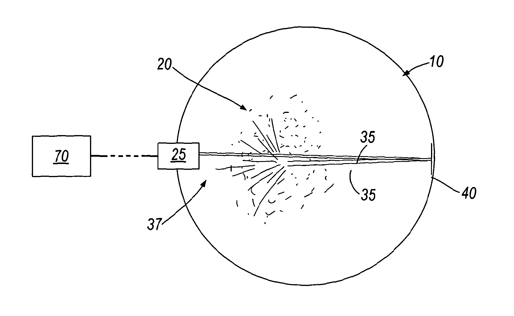
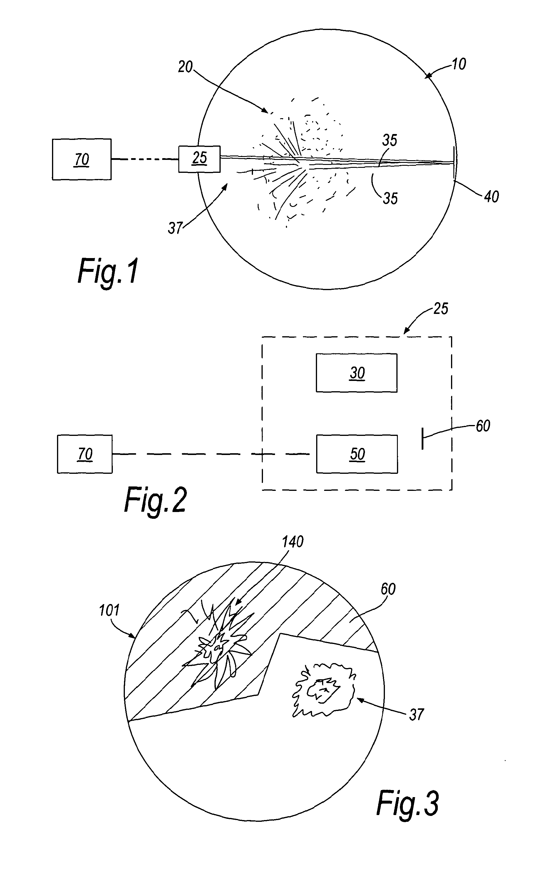
[0049]In a first example embodiment of the invention, a stack 10 contains a flow of particles 20. In a wall of the stack 10, there is mounted a particle monitor housing 25. On the wall of the stack 10 opposite the housing 25 there is mounted a mirror 40. In this example embodiment, the mirror 40 is a plane mirror, but, in alternative embodiments, other forms of reflector may be used. The laser beam 35 is emitted from the housing 25 and reflected back towards the housing 25 by the mirror. The beam 35 is scattered from the particles 20 flowing in the stack 10. An image of the light 37 scattered from the particles 10 is obtained. The image is passed to the data processing apparatus 70.

[0050]The housing 25 contains a laser 30 and an imager 50. The laser beam 35 is emitted by the laser 30, and the scattered light 37 is imaged by the imager 50. The image of the scattered light 37 is passed to data processing apparatus 70 from the imager 50. In this example embodiment, light scattered from...


PUM


Abstract

A method of monitoring particles in a stack comprises generating on a first side of the stack a beam of light directed towards a second, opposite, side of the stack. The beam is reflected back towards the first side of the stack and through the particles in the stack. An image is obtained of light scattered from the particles. The image is obtained using an imager positioned and oriented to have a field of view that includes unwanted scattered light. The method includes the step of blocking the unwanted scattered light from the image.

Description

FIELD OF THE INVENTION[0001]The present invention concerns an apparatus and method for monitoring particles in a stack. More particularly, the invention concerns an apparatus and method for monitoring particles in a stack by using a light source.[0002]The term “stack” as used herein refers to a volume through which a gas can pass, for example a chimney, tube, flue, duct or the like.BACKGROUND OF THE INVENTION[0003]Prior-art methods of monitoring particles in a stack include both electrical and optical methods. In a typical optical method, a beam of light from a laser source is directed across the stack (which is typically of diameter 0.5 m to 10 m). Particles in the stack scatter the laser beam over all solid angles with an angle-dependent intensity typically enhanced in a direction of scatter around the forward direction of an incident beam. A portion of the scattered light is collected by a simple telescope and focused onto a photo-detector; the portion of light collected varies i...

Claims


Application Information

Patent Timeline
IPC IPC(8): H04N7/18
CPCG01N15/0211G01N21/53G01N2021/4704G01N2015/0693G01N2015/0046G01N15/075
Inventor MILLINGTON, ROGER BRADLEYUNITT, DAVID CHRISTOPHER
Owner POLLUTION CONTROL & MEASUREMENT EURO
Features
  • Generate Ideas
  • Intellectual Property
  • Life Sciences
  • Materials
  • Tech Scout
  • Unparalleled Data Quality
  • Higher Quality Content
  • 60% Fewer Hallucinations
Learn More