Groove machining apparatus for insulating spacer and groove machining method for the same

a technology of machining apparatus and groove, which is applied in the direction of metal working apparatus, metal-working machine components, manufacturing tools, etc., can solve the problems of unevenness between the surface machined by the grooving rotary blade and the surface, the speed of the conveying cassette is restricted, and the production cost is high, etc., to achieve excellent smoothness, efficient groove formation, and suppress burring and fuzzing

Inactive Publication Date: 2013-02-28
IDEMITSU IND
View PDF11 Cites 5 Cited by
  • Summary
  • Abstract
  • Description
  • Claims
  • Application Information

AI Technical Summary

Benefits of technology

[0009]Thus, the grooving rotary blade comes into contact with the insulating spacer in a slanting state, which has the disadvantage that the conveyance speed of the cassette is restricted, and the productivity is low. Moreover, since surfaces machined by the serrated rotary blades have low smoothness and the cutting rotary blades and the grooving rotary blade have different axes, when the grooving rotary blade wears, a step (unevenness) will occur between the surface machined by the grooving rotary blade and the surfaces cut by the cutting rotary blades. Accordingly, the resistance of the passage for cooling oil will change, leading to a flow of the cooling oil different from the flow that has been simulated in advance, and therefore there is a risk that the required cooling effect may not be achieved. Furthermore, since pressboard is produced by laminating and compressing wet paper, the serrated rotary blades are likely to leave a burr or fuzz on the machined surface of the grooves, and if the burr or fuzz that has been left exfoliate as a result of long-term use, the exfoliated particles will mix into the cooling oil as foreign matter and accelerate clogging of a filter. Thus, there have been problems in that the yield of insulating spacers is low, and postprocessing for removing the step, burr or fuzz left on the machined surface of the grooves is necessary, thus increasing the cost.
[0020]In the present invention, it is preferable that one or more spacers can be disposed between the left-hand cutting blade and the right-hand cutting blade. This makes it possible to form grooves of any groove width between the minimum width that is obtained when the left-hand cutting blade and the right-hand cutting blade are directly placed together and the maximum width that is obtained when an inner edge of the cutting edge of the flat blade of the left-hand cutting blade and an inner edge of the cutting edge of the flat blade of the right-hand cutting blade slightly overlap with each other.

Problems solved by technology

Thus, the grooving rotary blade comes into contact with the insulating spacer in a slanting state, which has the disadvantage that the conveyance speed of the cassette is restricted, and the productivity is low.
Moreover, since surfaces machined by the serrated rotary blades have low smoothness and the cutting rotary blades and the grooving rotary blade have different axes, when the grooving rotary blade wears, a step (unevenness) will occur between the surface machined by the grooving rotary blade and the surfaces cut by the cutting rotary blades.
Accordingly, the resistance of the passage for cooling oil will change, leading to a flow of the cooling oil different from the flow that has been simulated in advance, and therefore there is a risk that the required cooling effect may not be achieved.
Furthermore, since pressboard is produced by laminating and compressing wet paper, the serrated rotary blades are likely to leave a burr or fuzz on the machined surface of the grooves, and if the burr or fuzz that has been left exfoliate as a result of long-term use, the exfoliated particles will mix into the cooling oil as foreign matter and accelerate clogging of a filter.
Thus, there have been problems in that the yield of insulating spacers is low, and postprocessing for removing the step, burr or fuzz left on the machined surface of the grooves is necessary, thus increasing the cost.

Method used


Image

  • Groove machining apparatus for insulating spacer and groove machining method for the same
  • Groove machining apparatus for insulating spacer and groove machining method for the same
  • Groove machining apparatus for insulating spacer and groove machining method for the same

Examples


Embodiment Construction

[0033]Hereinafter, an embodiment of the present invention will be described with reference to the drawings.

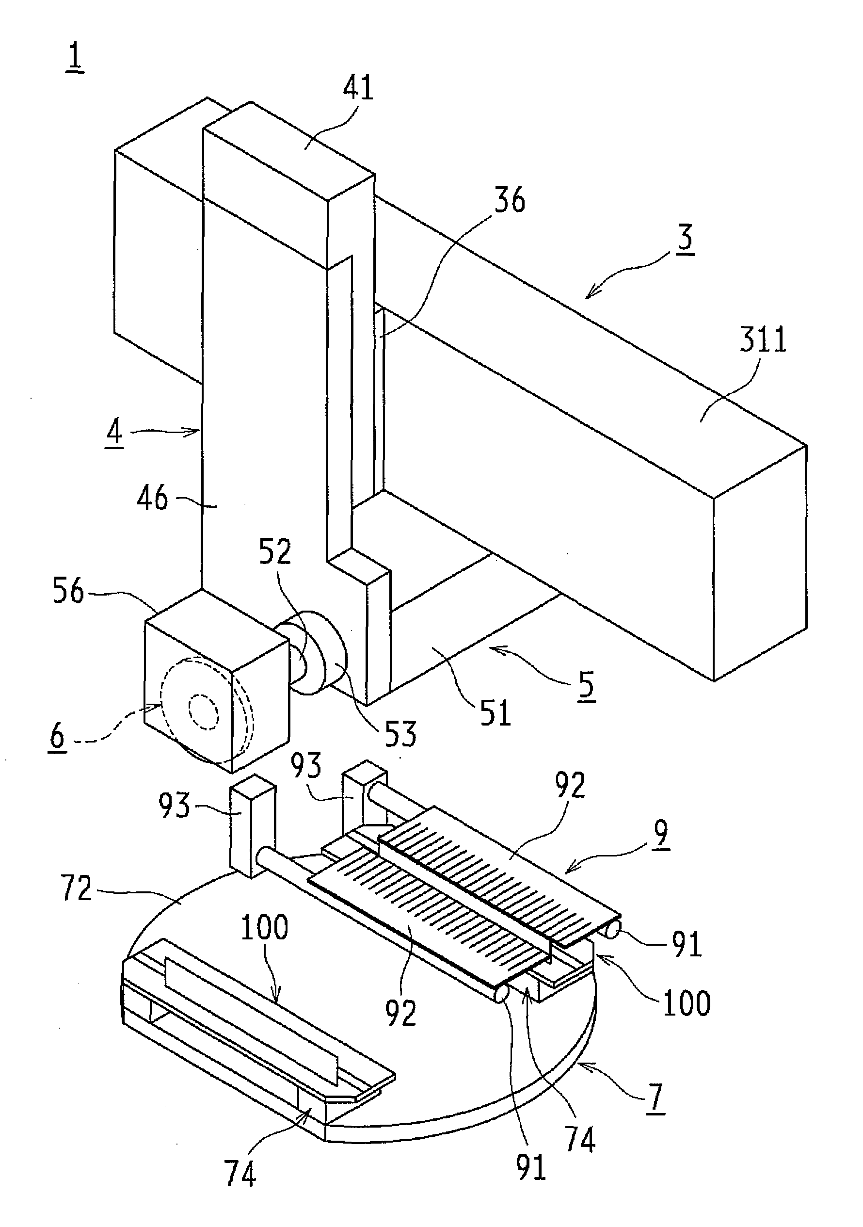
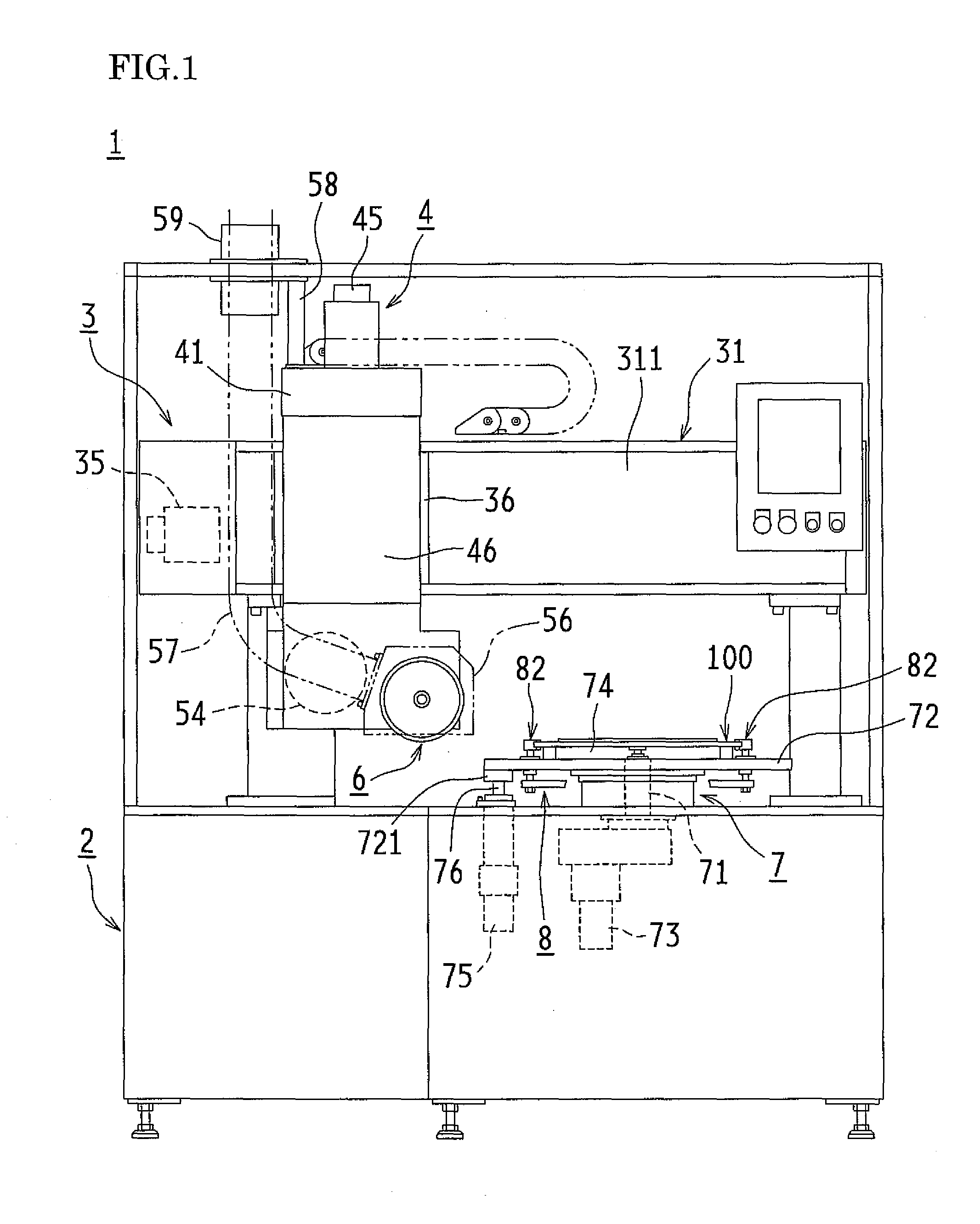
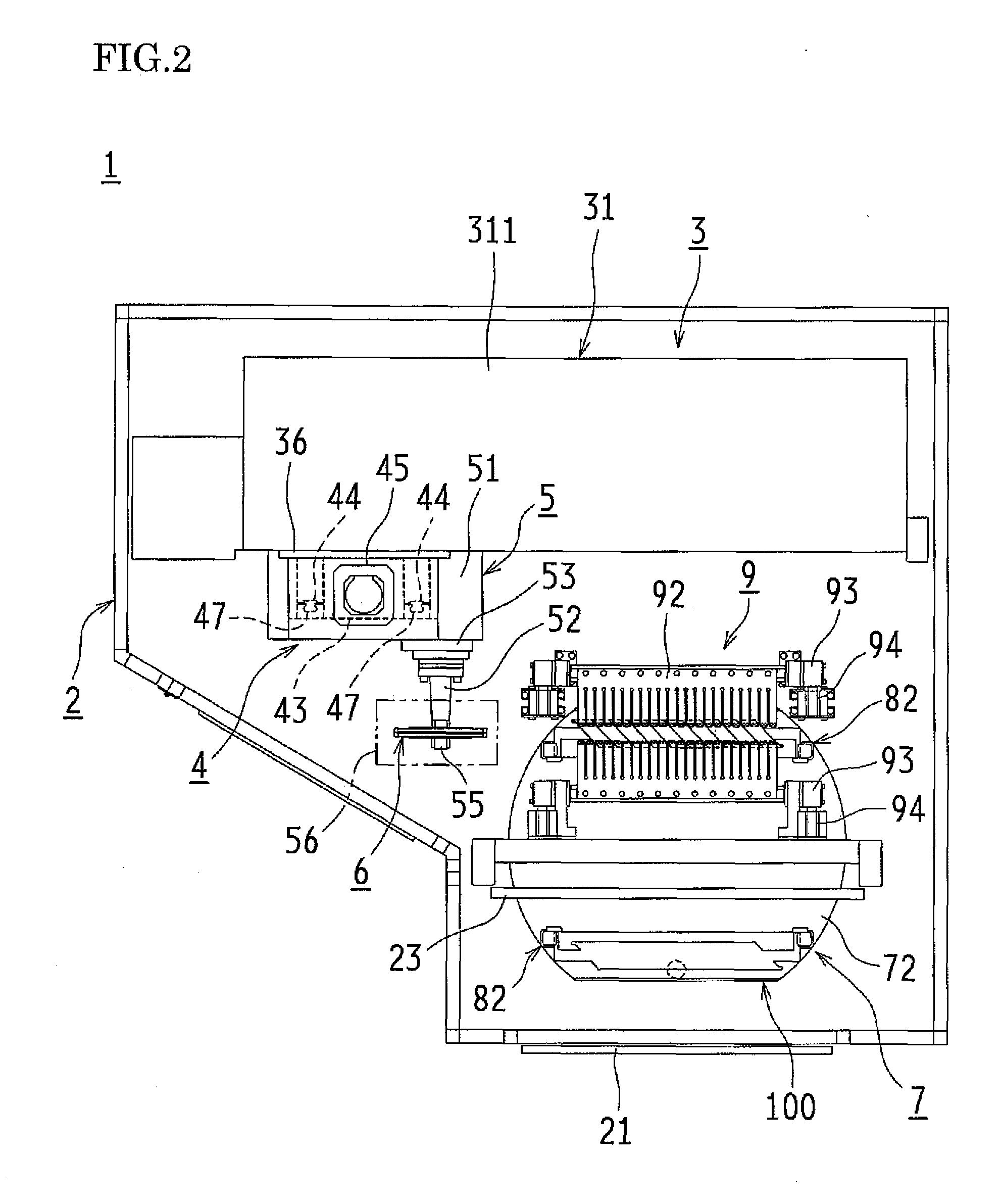
[0034]FIGS. 1 to 4 show an embodiment of a groove machining apparatus 1 according to the present invention.

[0035]It should be noted that before describing the groove machining apparatus 1, a cassette 100 that is used in machining grooves in insulating spacers S will be described. This cassette 100 is, as shown in FIG. 10, an approximately rectangular plate whose front left and right corners are cut off so as to conform to an outer circumferential circle of a rotary table 72 (described later) when viewed from above, and in order that a plurality of (ten in an embodiment) insulating spacers S can be aligned in a right-left direction when their short sides are regarded as the bases, a parallelogram-shaped recess 101 having a horizontal dimension that is multiple times longer than the length of a short side of each insulating spacer S, a vertical dimension that corresponds to the h...


PUM

PropertyMeasurementUnit
rotationaaaaaaaaaa
widthaaaaaaaaaa
depthaaaaaaaaaa

Abstract

A groove machining apparatus for an insulating spacer includes a cutting blade that is removably fixed to a rotation shaft rotatable around a horizontal axis and movable in a right-left direction and in an up-down direction and mounts for a cassette that are fixed in a loading / unloading position opposing an entrance through which the cassette can be loaded / unloaded and in a working position 180 degrees apart from the loading / unloading position and facing the cutting blade, respectively, on a rotary table. The apparatus includes positioning devices that are respectively located in the vicinity of the mounts to position and fix the cassette to the mounts, and a clamping device that corresponds to the cassette in the working position and presses opposing edges in a front-back direction of a plurality of insulating spacers aligned on the cassette.

Description

CROSS-REFERENCE TO RELATED APPLICATIONS[0001]This application claims priority under 35 U.S.C. §119(a) on Patent Application No. 2011-182776 filed in Japan on Aug. 24, 2011, the entire contents of which are herein incorporated by reference.BACKGROUND OF THE INVENTION[0002]1. Field of the Invention[0003]The present invention relates to a groove machining apparatus that forms grooves for oil passages in insulating spacers of oil-filled transformers and a groove machining method for such groove machining apparatuses.[0004]2. Description of the Related Art[0005]Generally, coils of oil-filled transformers are produced by winding a copper wire on which thin insulating paper of several tens of microns is wound into the coil form. Moreover, insulators composed of an insulating plate formed by cutting pressboard having a thickness of several millimeters corresponding to the coil into a predetermined shape and multiple insulating spacers attached to set positions on the insulating plate are ar...

Claims


Application Information

Patent Timeline
Patent Type & Authority Applications(United States)
IPC IPC(8): B26D3/06B23Q3/06H01F41/00
CPCY10T29/5196B23C3/30B23C2210/285B23C5/08B23C2210/287Y10T29/5124B23C2210/244Y10T83/0304
Inventor TAKAHASHI, MASAHIRO
Owner IDEMITSU IND
Why Eureka
Try Eureka