Method and apparatus for Anti-biofouling of a protected surface in liquid environments

a technology of anti-biofouling and protective surface, applied in the direction of water/sewage treatment by substance addition, energy-based chemical/physical/physico-chemical processes, hulls, etc., can solve the problems of increasing drag of water operations, high cost and ship down time, and the need to apply anti-biofouling coatings. to prevent biofouling, prevent biofouling, and reduce or eliminate the need

Active Publication Date: 2013-02-28
RAYTHEON CO
View PDF19 Cites 180 Cited by
  • Summary
  • Abstract
  • Description
  • Claims
  • Application Information

AI Technical Summary

Benefits of technology

[0012]The present invention provides means to prevent biofouling of surface, e.g., an opaque surface, disposed in the water without using chemicals, wherein the system can prevent biofouling to a degree that would reduce or eliminate the need to remove the surface, e.g., a surface upon a vessel, from the water.

Problems solved by technology

As is known, boats, ships, and other vessels that experience biofouling are subject to increased drag when operating in the water.
However, anti-biofouling coatings tend to degrade with time and need to be reapplied, for example, every few years.
In order to reapply an anti-biofouling coating, a ship must be put to dry dock for the operation, resulting in high cost and ship down time.
Although the effects of such chemical systems are temporary, only lasting a few months, the effect on the environment is larger than desired for an anti-biofouling system.
Furthermore the chemical release mechanisms are subjected to the ocean environment, e.g., pressure, resulting in reduced reliability.
Ultraviolet light in a UVA band (about 320-400 nm) can cause skin damage and may cause melanomatous (skin cancer).
Ultraviolet light in a UVC band (below about 280 nm) is the strongest, having the greatest energy per photon (eV), and is potentially the most harmful form.

Method used


Image

  • Method and apparatus for Anti-biofouling of a protected surface in liquid environments
  • Method and apparatus for Anti-biofouling of a protected surface in liquid environments
  • Method and apparatus for Anti-biofouling of a protected surface in liquid environments

Examples


Embodiment Construction

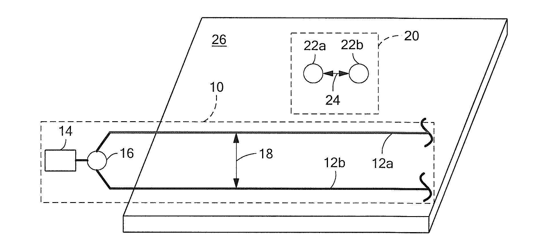
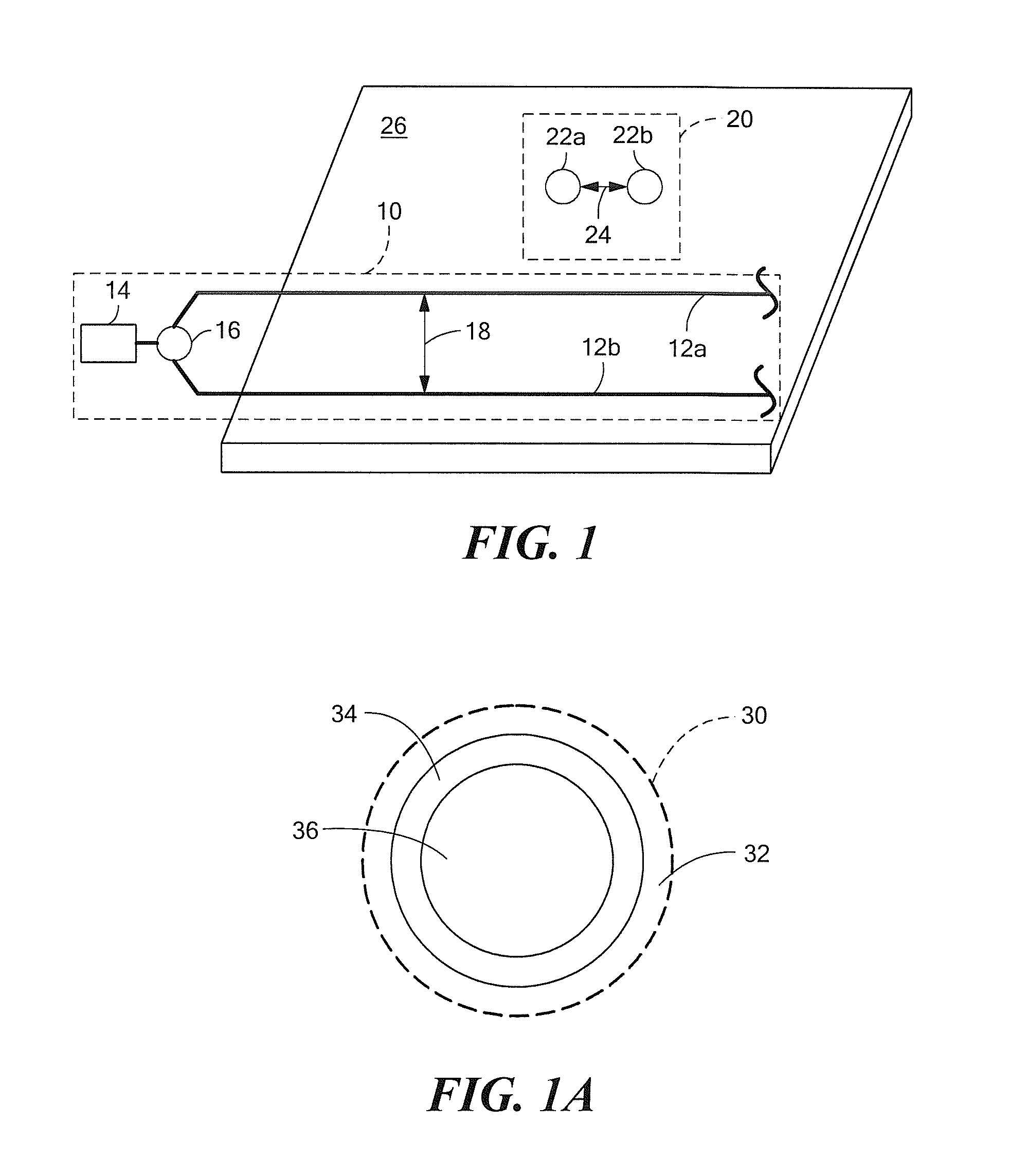
[0028]Before describing the present invention, some introductory concepts and terminology are explained. As used herein, the term “protected surface” refers to a surface that would become fouled with organisms were it not protected by one of the embodiments of the system described below.

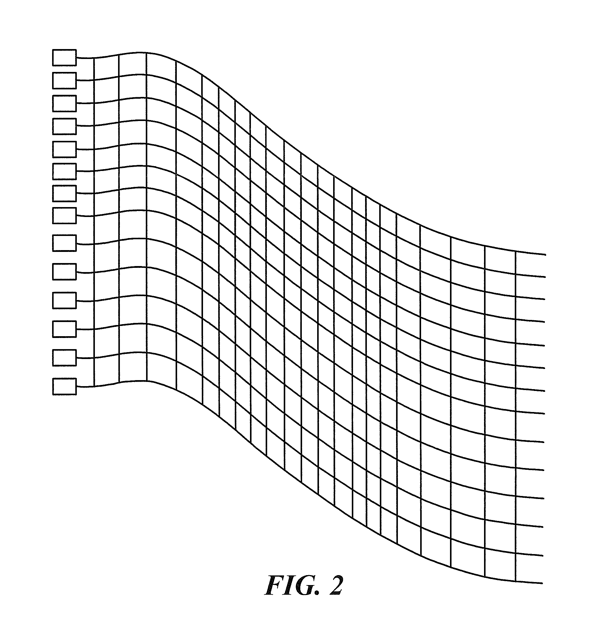
[0029]As used herein, the term “optical medium” is used to describe an ultraviolet carrying and / or ultraviolet emitting part of the systems described below. As will become apparent, the optical medium is used to distribute the ultraviolet light to protect the protected surface from fouling with organisms. As will also become apparent, there are many embodiments of the optical medium.

[0030]In some embodiments, the optical medium is coupled to receive ultraviolet light from one or more ultraviolet light sources. In some other embodiments, the optical medium is conjoined with one or more ultraviolet light sources.

[0031]As used herein, the term “ultraviolet light source” is used to describe any emitter o...


PUM

PropertyMeasurementUnit
wavelengthaaaaaaaaaa
wavelengthsaaaaaaaaaa

Abstract

A system includes a UV light source and an optical medium coupled to receive UV light from the UV light source. The optical medium is configured to emit UV light proximate to a surface to be protected from biofouling. A method corresponds to the system.

Description

FIELD OF THE INVENTION[0001]This invention relates generally to anti-biofouling apparatus and, more particularly, to an apparatus for keeping free of biological fouling a surface, for example, a ship hull, immersed in a liquid, for example, the ocean.BACKGROUND OF THE INVENTION[0002]Underwater objects, particularly underwater objects that are in the water for long periods of time, have external surfaces that are subject to so-called “biofouling.” A used herein, the term “biofouling” is used to describe an attachment of organisms that live in the liquid, e.g., in the ocean, to surfaces, particularly to man-made surfaces. The organisms can be small, for example, algae, or larger, for example, barnacles.[0003]Detrimental effects of biofouling to man-made surfaces are well known and wide-ranging. As is known, boats, ships, and other vessels that experience biofouling are subject to increased drag when operating in the water.[0004]As is known, some types of coatings, for example, anti-bi...

Claims


Application Information

Patent Timeline
Patent Type & Authority Applications(United States)
IPC IPC(8): G21K5/02
CPCG02B6/102B63B59/04G02B6/001G02B6/0048C02F2303/20B01J2219/0877B08B17/02B63B59/08C02F1/325B01J19/123
Inventor THOREN, MATTHEW D.PIPER, ANDREW M.
Owner RAYTHEON CO
Why Eureka
Try Eureka