Light emitting device, super-luminescent diode, and projector

a technology of superluminescent diodes and light emitting devices, which is applied in the direction of diodes, instruments, projectors, etc., can solve the problem of not being able to apply the technology to the type of projector, and achieve the effect of easy alignment of lens arrays

Inactive Publication Date: 2013-02-28
SEIKO EPSON CORP
View PDF11 Cites 12 Cited by
  • Summary
  • Abstract
  • Description
  • Claims
  • Application Information

AI Technical Summary

Benefits of technology

[0030]According to such a projector, the alignment of the lens arrays is easy, and the l

Problems solved by technology

In the technology described in Document 1, it is difficult to arrange the plurality of light emitting sections with intervals corresponding to a var

Method used


Image

  • Light emitting device, super-luminescent diode, and projector
  • Light emitting device, super-luminescent diode, and projector
  • Light emitting device, super-luminescent diode, and projector

Examples


Embodiment Construction

[0055]Some exemplary embodiments of the invention will hereinafter be described with reference to the accompanying drawings.

1. Light Emitting Device

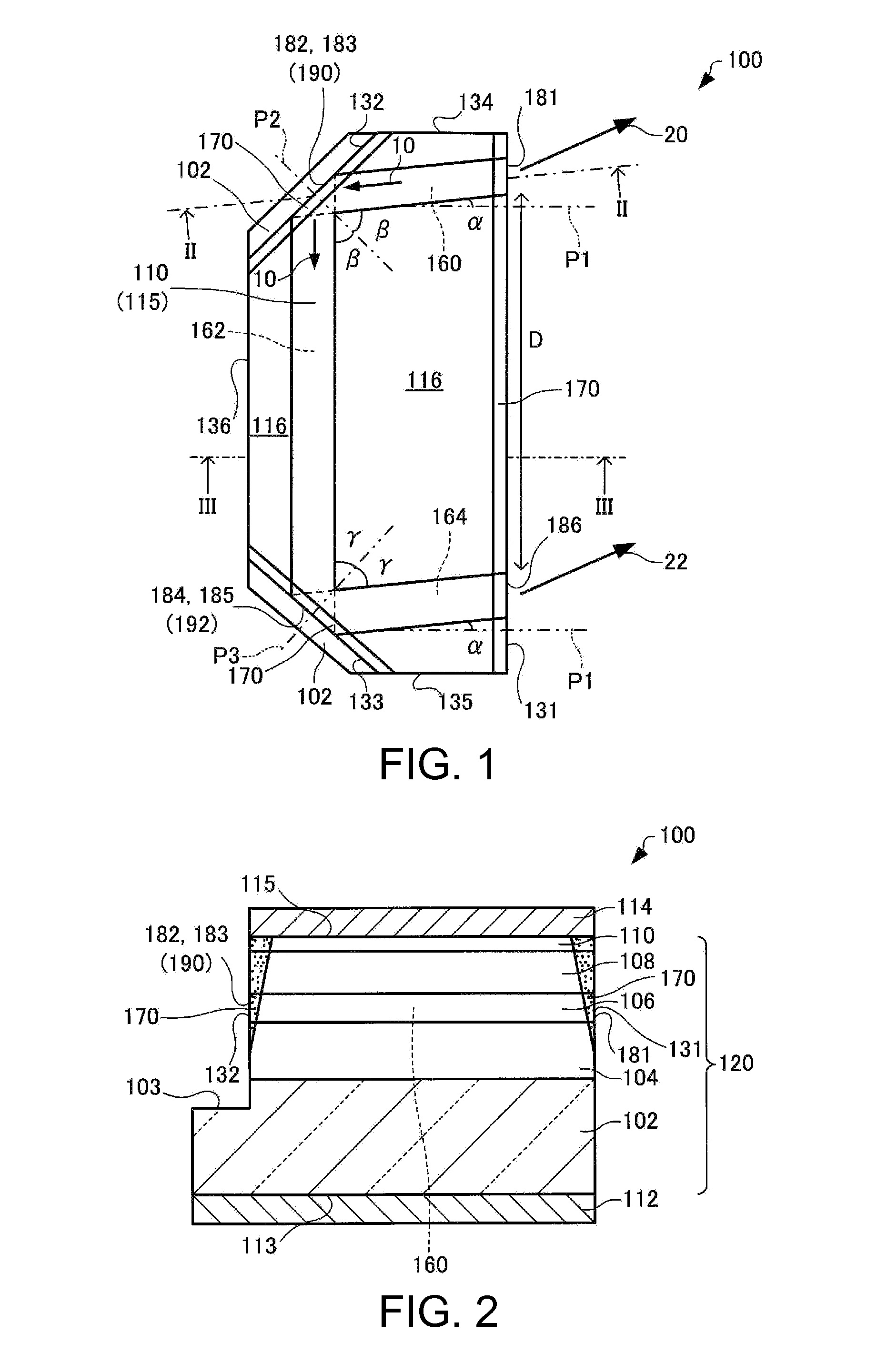
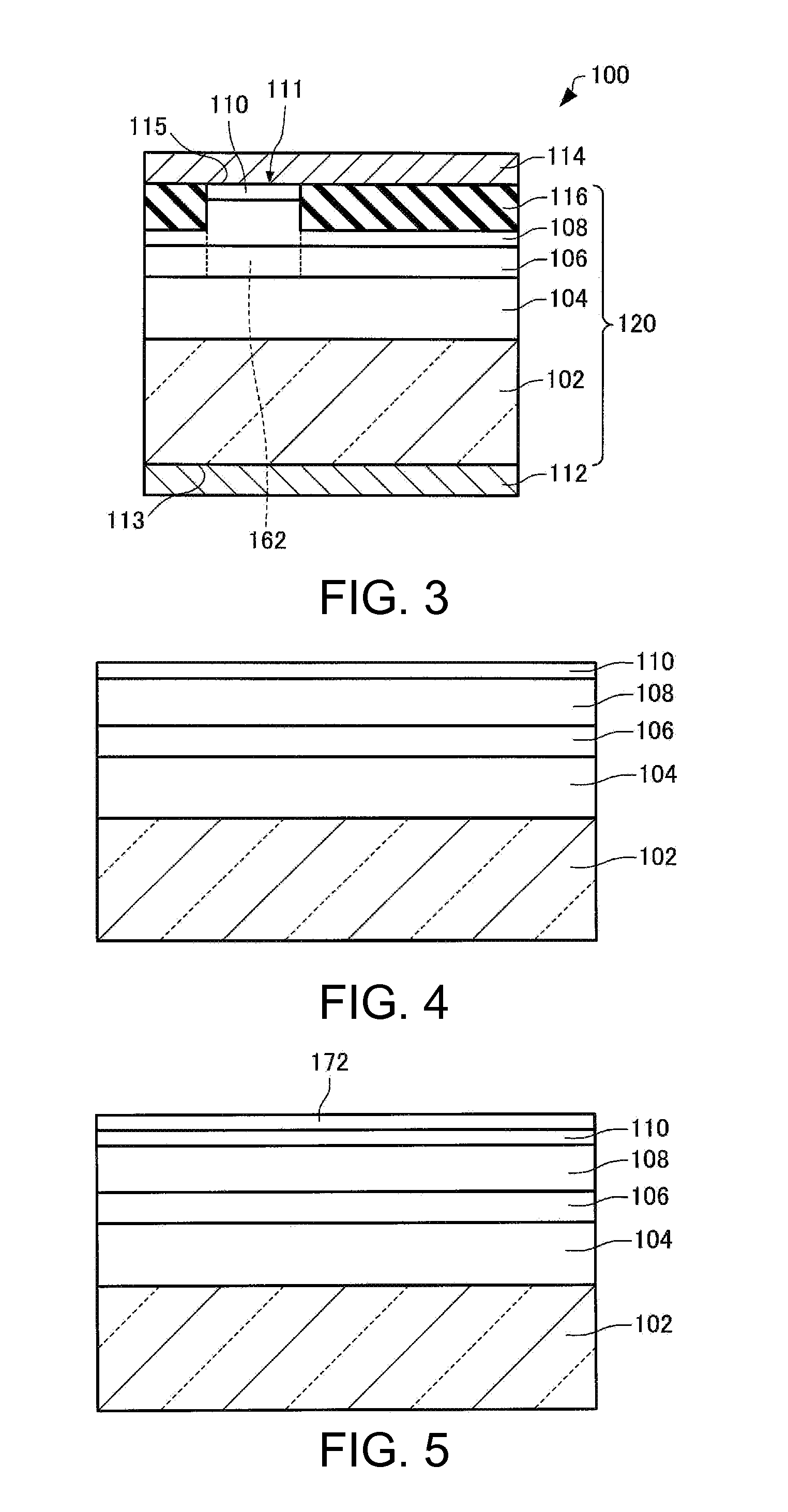
[0056]Firstly, a light emitting device according to the present embodiment will be explained with reference to the accompanying drawings. FIG. 1 is a plan view schematically showing the light emitting device 100 according to the present embodiment. FIG. 2 is a cross-sectional view along the line II-II shown in FIG. 1, and schematically shows the light emitting device 100 according to the present embodiment. FIG. 3 is a cross-sectional view along the line III-III shown in FIG. 1, and schematically shows the light emitting device 100 according to the present embodiment. It should be noted that in FIG. 1, a second electrode 114 is omitted from drawing for the sake of convenience.

[0057]The case in which the light emitting device 100 is an SLD of the InGaAlP type (red) will be explained below. Unlike the semiconductor laser, in the SLD, laser...


PUM


Abstract

A light emitting device includes a first layer that generates light by an injection current, the first layer is provided with a first optical waveguide extending from a first light emitting section disposed on a first side surface to a first light reflecting section disposed on a second side surface, a second optical waveguide extending from the first light reflecting section to a second light reflecting section disposed on a third side surface, and a third optical waveguide extending from the second light reflecting section to a second light emitting section disposed on the first side surface, an element of the group II or the group XII is diffused in the first light reflecting section and the second light reflecting section, and a first light emitted from the first light emitting section and a second light emitted from the second light emitting section are emitted in the same direction.

Description

BACKGROUND[0001]1. Technical Field[0002]The present invention relates to a light emitting device, a super-luminescent diode, and a projector.[0003]2. Related Art[0004]A super-luminescent diode (hereinafter also referred to as an “SLD”) is a semiconductor light emitting device capable of providing an output up to several hundreds of mW with a single device similarly to a semiconductor laser, while showing a broadband spectrum and thus being incoherent shape similarly to an ordinary light emitting diode.[0005]The SLD can be used as, for example, a light source of a projector, and for realizing a small-sized and high-brightness projector, it is required to use a light source with high light output and low etendue. In order to achieve this, it is preferable that the lights emitted from a plurality of gain regions travel in the same direction. In JP-A-2010-3833 (Document 1), by combining the gain region having a linear shape and the gain region having a winded shape at a reflection surfa...

Claims


Application Information

Patent Timeline
IPC IPC(8): G03B21/14G02B6/30
CPCG02B6/4298H01L33/0045G03B21/2033G03B21/2006G02B6/4214G03B21/006G03B21/208
Inventor MOCHIZUKI, MASAMITSU
Owner SEIKO EPSON CORP
Why Eureka
Try Eureka