
Apparatus and method for processing an audio signal using patch border alignment

an audio signal and patch border technology, applied in the field of apparatus and method for processing an audio signal using patch border alignment, can solve the problems of high computational complexity, high complexity, and still much higher complexity than the trivial ssb based hfr method, and achieve efficient time and frequency domain operations, improve audio quality, and reduce complexity

Active Publication Date: 2013-02-28
FRAUNHOFER GESELLSCHAFT ZUR FOERDERUNG DER ANGEWANDTEN FORSCHUNG EV +1
View PDF0 Cites 85 Cited by
  • Summary
  • Abstract
  • Description
  • Claims
  • Application Information

AI Technical Summary

Benefits of technology

The present invention aims to improve the quality of audio source coding systems and digital effect processors. It does this by avoiding misaligned patch borders and frequency bands when analyzing parametric data. Instead, the method aligns the spectral borders of the HFR generated signals to the envelope adjustment frequency table and the spectral borders of the limiter tool, resulting in better high quality harmonic HFR methods and sub-band block based harmonic HFR methods. This also reduces the computational complexity of the subband block based harmonic HFR method by efficient filtering and sampling rate conversion of the input signals prior to the HFR filter bank analysis stages.

Problems solved by technology

Given a core signal with low bandwidth, a dissonant ringing artifact can result from SSB transposition.
The obvious drawback is that the computational complexity can become high.
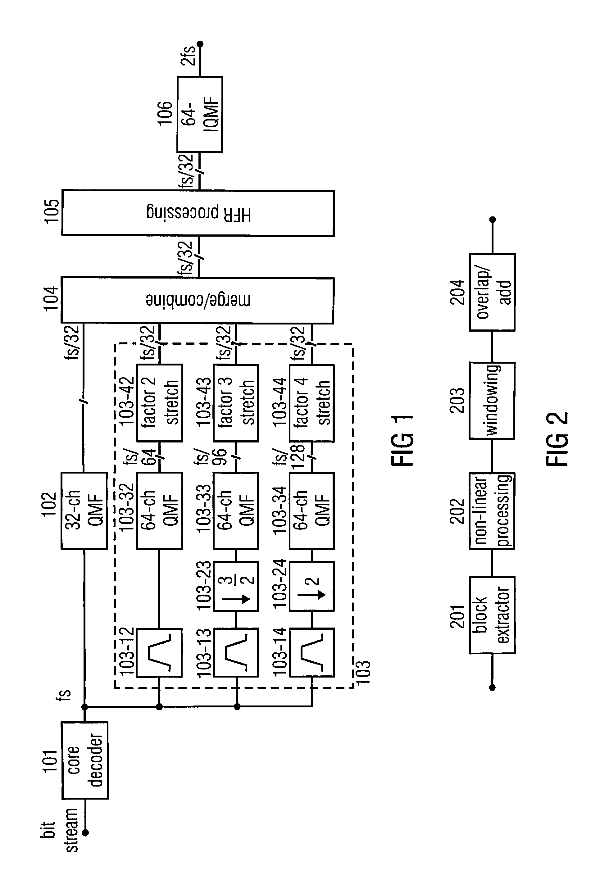
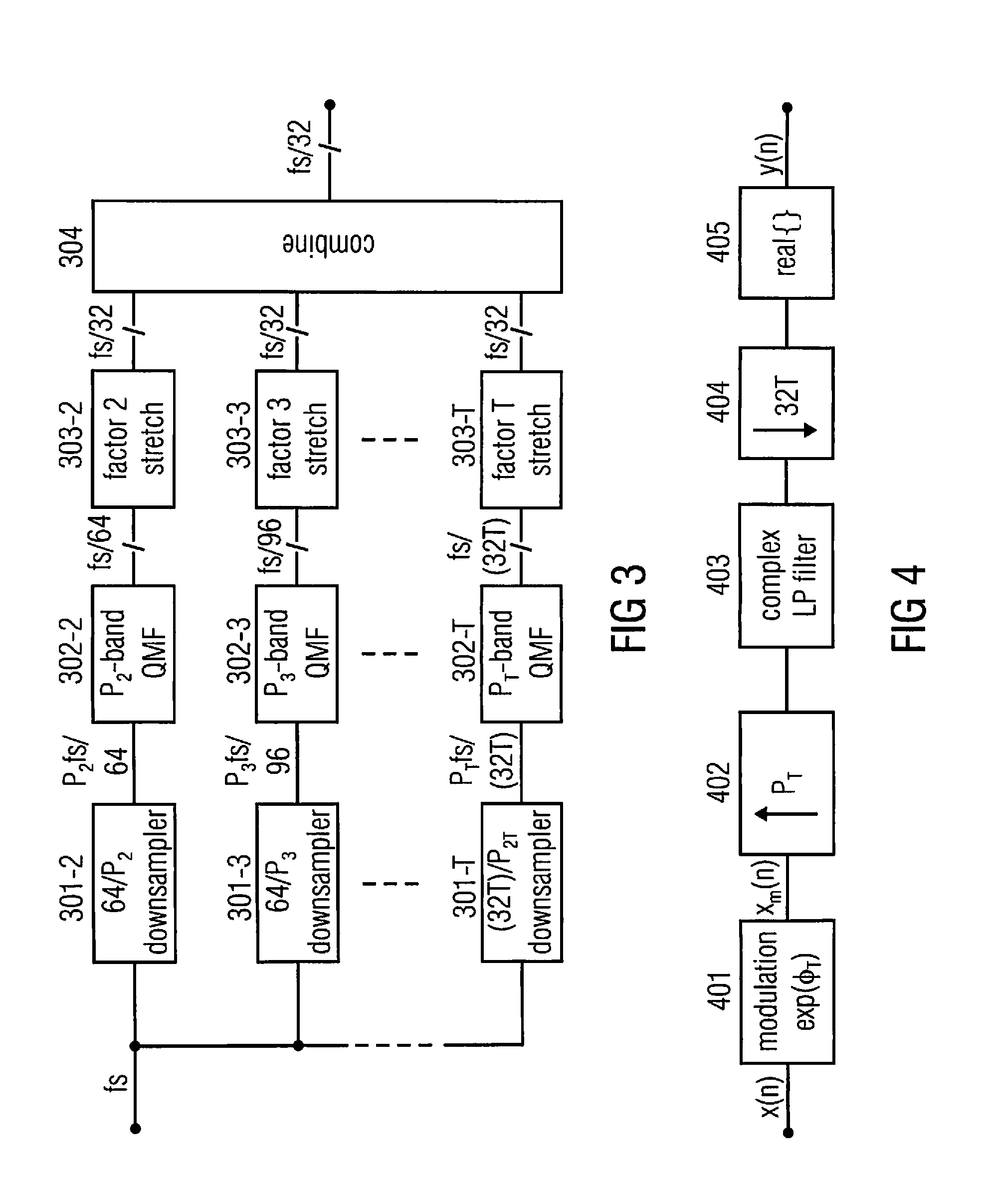
However, the complexity is still much higher than for the trivial SSB based HFR methods, since a plurality of analysis filter banks, each processing signals of different transposition orders T, may be used in a typical HFR application in order to synthesize the bandwidth that may be used.
Storage or transmission of audio signals is often subject to strict bitrate constraints.
In the past, coders were forced to drastically reduce the transmitted audio bandwidth when only a very low bitrate was available.
Albeit being beneficial for many tonal signals, this method called “harmonic bandwidth extension” (HBE) is prone to quality degradations of transients contained in the audio signal [14], since vertical coherence over sub-bands is not guaranteed to be preserved in the standard phase vocoder algorithm and, moreover, the re-calculation of the phases has to be performed on time blocks of a transform or, alternatively of a filter bank.
However, since the BWE algorithm is performed on the decoder side of a codec chain, computational complexity is a serious issue.
State-of-the-art methods, especially the phase vocoder based HBE, comes at the prize of a largely increased computational complexity compared to SSB based methods.
Moreover, the computational complexity is significantly increased over the computational very simple SSB copy-up method.
This is due to the fact that a high sampling rate means a high complexity and a low sampling rate generally means low complexity due to the reduced number of operations that may be performed.
On the other hand, however, the situation in bandwidth extension applications is particularly so that the sampling rate of the core coder output signal will typically be so low that this sampling rate is too low for a full bandwidth signal.
Hence, the size of the filterbanks, i.e. whether the filterbank is a 32 channel filterbank, a 64 channel filterbank or even a filterbank with a higher number of channels will significantly influence the complexity of the audio processing algorithm.
Generally, one can say that a high number of filterbank channel involves more processing operations and, therefore, higher complexity then a small number of filterbank channels.
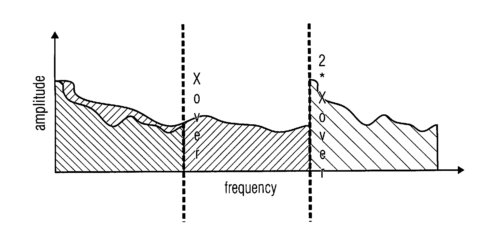
A disadvantage of this procedure, however, is that a misalignment between the frequency bands, for which the parametric data sets are provided on the one hand and the spectral borders of a patch on the other hand, can occur.
Particularly in situations where the spectral energy strongly changes in the vicinity of a patch border, artifacts may arise specifically in this region, which degrade the quality of the bandwidth extended signal.

Method used


Image

  • Apparatus and method for processing an audio signal using patch border alignment
  • Apparatus and method for processing an audio signal using patch border alignment
  • Apparatus and method for processing an audio signal using patch border alignment

Examples


Embodiment Construction

[0064]The below-described embodiments are merely illustrative and may provide a lower complexity of a QMF transposer by efficient time and frequency domain operations, and improved audio quality of both QMF and DFT based harmonic SBR by spectral alignment. It is understood that modifications and variations of the arrangements and the details described herein will be apparent to others skilled in the art. It is the intent, therefore, to be limited only by the scope of the impending patent claims and not by the specific details presented by way of description and explanation of the embodiments herein.

[0065]FIG. 23 illustrates an embodiment of an apparatus for processing an audio signal 2300 to generate a bandwidth extended signal having a high frequency part and a low frequency part using parametric data for the high frequency part, where the parametric data relates to frequency bands of the high frequency part. The apparatus comprises a patch border calculator 2302 for calculating a ...


PUM


Abstract

Apparatus for processing an audio signal to generate a bandwidth extended signal having a high frequency part and a low frequency part using parametric data for the high frequency part, the parametric data relating to frequency bands of the high frequency part includes a patch border calculator for calculating a patch border such that the patch border coincides with a frequency band border of the frequency bands. The apparatus further includes a patcher for generating a patched signal using the audio signal and the patch border.

Description

CROSS-REFERENCE TO RELATED APPLICATIONS[0001]This application is a continuation of copending International Application No. PCT / EP2011 / 053313, filed Mar. 4, 2011, which is incorporated herein by reference in its entirety, and additionally claims priority from U.S. Application No. 61 / 312,127, filed Mar. 9, 2010, which is also incorporated herein by reference in its entirety.[0002]The present invention relates to audio source coding systems which make use of a harmonic transposition method for high frequency reconstruction (HFR), and to digital effect processors, e.g. so-called exciters, where generation of harmonic distortion adds brightness to the processed signal, and to time stretchers, where the duration of a signal is extended while maintaining the spectral content of the original.BACKGROUND OF THE INVENTION[0003]In PCT WO 98 / 57436 the concept of transposition was established as a method to recreate a high frequency band from a lower frequency band of an audio signal. A substanti...

Claims


Application Information

Patent Timeline
Patent Type & Authority Applications(United States)
IPC IPC(8): H04R29/00G10L19/02G10L21/038G10L21/04
CPCG10L19/0204G10L19/008G10L21/04G10L21/038G10L21/0232
Inventor NAGEL, FREDERIKDISCH, SASCHAWILDE, STEPHANVILLEMOES, LARSEKSTRAND, PER
Owner FRAUNHOFER GESELLSCHAFT ZUR FOERDERUNG DER ANGEWANDTEN FORSCHUNG EV
Learn More