Stereolithography Machine

a stereolithography machine and lithography technology, applied in auxillary shaping apparatus, manufacturing enclosures, manufacturing tools, etc., can solve the problems of difficult successive lifting of objects, progressively becoming opaque, stereolithography machines of known types described, etc., to reduce the cost, increase the processing cycle, and prolong the duration

Active Publication Date: 2013-02-28
DWS SRL
View PDF1 Cites 17 Cited by
  • Summary
  • Abstract
  • Description
  • Claims
  • Application Information

AI Technical Summary

Benefits of technology

[0030]Advantageously, a longer duration of the tank makes it possible to use to the same tank to carry out more processing cycles compared to the machines of known type.
[0031]Therefore, advantageously, it is possible to distribute the cost of each tank on a larger number of three-dimensional objects, thus reducing their cost.
[0032]Still advantageously, the possibility to produce higher three-dimensional objects makes the machine of the invention more versatile than the machines of known type.

Problems solved by technology

This technique poses the drawback that the resin that is solidified tends to adhere to the bottom of the tank, thus making it difficult to successively lift the object.
However, the covering layers of known type pose the drawback that they progressively tend to become opaque due to exposure to light.
The stereolithography machines of known type described above however pose the drawback that they require frequent replacements of the tank, in some cases even after each single processing cycle.
Obviously, changing the tank frequently means causing an additional cost that affects the final cost of the three-dimensional object.
This system poses the drawback that the control of the position of the tank with respect to the supporting plate depends on the motor, which however is not capable of maintaining the tank in a stable position in is case, for example, of impacts or vibrations during the construction process of the object.
Furthermore, the removal of the tank from the supporting plate requires the disassembly of a part of the machine, which makes the replacement of the tank rather complicated.

Method used


Image

  • Stereolithography Machine
  • Stereolithography Machine
  • Stereolithography Machine

Examples


Embodiment Construction

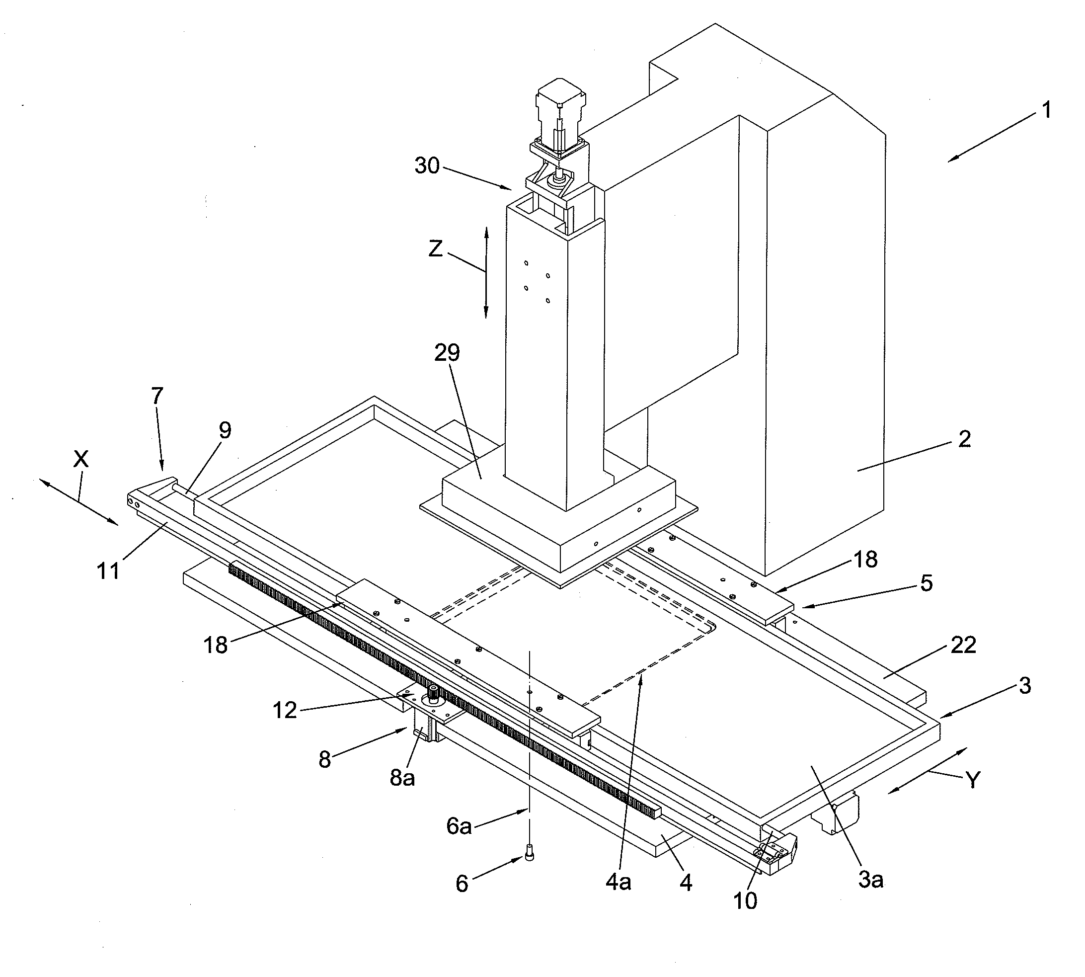
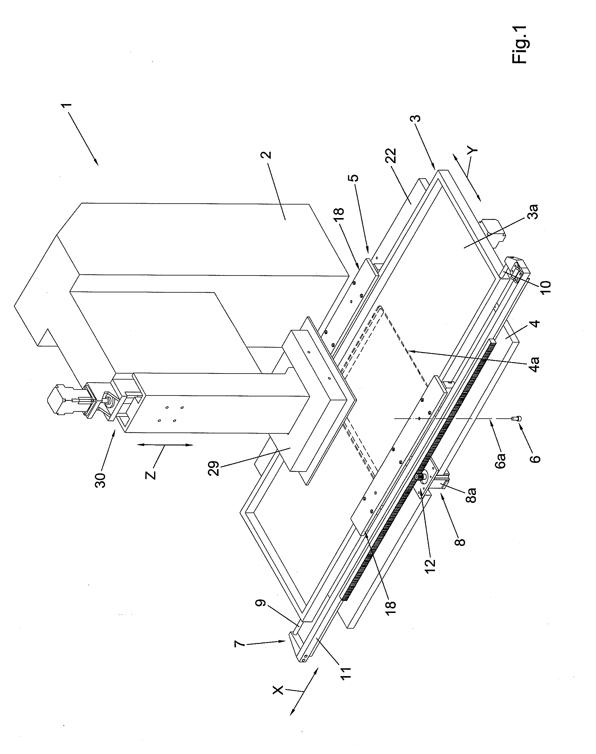
[0041]The stereolithography machine that is the subject of the invention, indicated as a whole by 1 in FIG. 1, comprises a supporting frame 2 associated with a supporting plate 4 that supports a tank 3 suited to contain a liquid substance.

[0042]The stereolithography machine 1 also comprises a stopping unit 5 suited to lock the tank 3 on the supporting plate 4 so as to define at least one firm resting position of the tank 3.

[0043]Emitter means 6 are also provided, which are suited to direct a is predefined electromagnetic radiation 6a towards the tank 3 when this is arranged in the above mentioned firm resting position, so as to obtain the selective solidification of the liquid substance.

[0044]Preferably but not necessarily, said liquid substance is a light-sensitive resin suited to polymerize when stimulated by light radiation and the predefined electromagnetic radiation 6a is a laser light beam.

[0045]The invention is particularly suitable for a stereolithography machine 1 where the...


PUM

PropertyMeasurementUnit
electromagnetic radiationaaaaaaaaaa
transparentaaaaaaaaaa
movementaaaaaaaaaa

Abstract

Stereolithography machine (1) comprising: a supporting frame (2); a tank (3) suited to contain a liquid substance; a supporting plate (4) associated with the supporting frame (2), suited to support the tank (3); a stopping unit (5) suited to firmly hold the tank (3) on the supporting plate (4) in a resting position; emitter means (6) suited to direct a predefined electromagnetic radiation (6a) towards the tank (3); a holding unit (7) of the tank (3) operatively associated with the supporting plate (4) through first actuator means (8) configured so as to move the tank (3) with respect to the supporting plate (4) according to a predefined trajectory of movement. The stopping unit (5) comprises second actuator means (17) that define for the stopping unit (5) an active configuration for holding the tank (3) and a rest configuration for releasing the tank (3).

Description

FIELD OF THE INVENTION[0001]The present invention concerns a stereolithography machine for the production of three-dimensional objects through solidification of a liquid substance.BACKGROUND OF THE INVENTION[0002]As is known, the stereolithography technique allows a three-dimensional object to be produced by superimposing a plurality of layers obtained from a substance that was initially liquid.[0003]Each layer of the three-dimensional object is obtained by exposing a corresponding layer of the above mentioned liquid substance to suitable electromagnetic stimulation that causes it to be selectively solidified through polymerization in the areas corresponding to the object to be obtained.[0004]According to a known embodiment, the above mentioned technique is implemented by means of stereolithography machines generally comprising a tank suited to contain a light-sensitive liquid resin, associated with a supporting plate.[0005]The machine also comprises an emitter suited to direct a li...

Claims


Application Information

Patent Timeline
Patent Type & Authority Applications(United States)
IPC IPC(8): B29C35/08
CPCB29C67/0066B29C67/0085B29C64/135B29C64/25B29C64/255B29C64/232B29C64/245B29C67/00
Inventor BUSATO, RENZO
Owner DWS SRL
Why Eureka
Try Eureka