Method for manufacturing a bending transducer, a micro pump and a micro valve, micro pump and micro valve

a technology of bending transducers and micro pumps, which is applied in the direction of machines/engines, flexible member pumps, positive displacement liquid engines, etc., can solve the problems of small stroke volumes, difficult to reduce dead volume and increase compression ratio, and is typically not possible to complete adaptation to the bend line. , to achieve the effect of high stroke volumes v, and high pre-bulging extents

Active Publication Date: 2013-03-07
FRAUNHOFER GESELLSCHAFT ZUR FOERDERUNG DER ANGEWANDTEN FORSCHUNG EV
View PDF3 Cites 16 Cited by
  • Summary
  • Abstract
  • Description
  • Claims
  • Application Information

AI Technical Summary

Benefits of technology

[0046]Methods for producing the pre-bulging of the membrane according to the present invention allow to implement particularly high extents of pre-bulging, e.g. large pre-bulging heights in relation to the lateral extension of the pump chamber, i.e. in relation to the diameter of the pump chamber, and, thus, facilitate not only high pump chamber vol

Problems solved by technology

The micro pumps described in EP 0 424 087 A1, however, are disadvantageous in that they either comprise considerably large dead volumes or only allow small strokes in the upward direction and thus only small stroke volumes.
When restricting the movement of the membrane to the downward movement it is difficult to reduce the dead volume and to increase the compression ratio.
This adaptation to the bend line of the pumping membrane is complex and costly with regard to production engineering, and furthermore a complete adaptation to the bend line is typically not possible because the pumping membrane deflects itself not completely symmetrically, for example, because of distortions of the pumping membrane due to the gluing process, so that gaps remain within the pump chamber that reduce the compression ratio.
Furthermore, the stroke volume of a standard actuator is limited by the boundary conditions, if the edges of the diaphragm are clamped.
Finally, with silicon this alignment can only partly be achieved by etching several steps into the wafer, which causes a high effort.
Micro pumps according to U.S. Pat. No. 5,759,014 are disadvantageous in that the dead volume c

Method used


Image

  • Method for manufacturing a bending transducer, a micro pump and a micro valve, micro pump and micro valve
  • Method for manufacturing a bending transducer, a micro pump and a micro valve, micro pump and micro valve
  • Method for manufacturing a bending transducer, a micro pump and a micro valve, micro pump and micro valve

Examples


Embodiment Construction

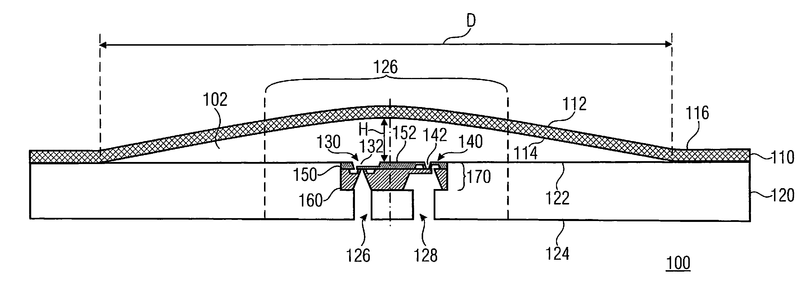
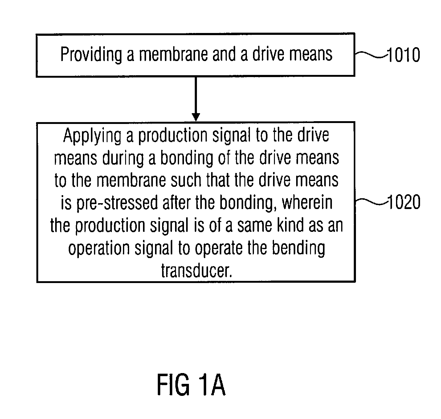
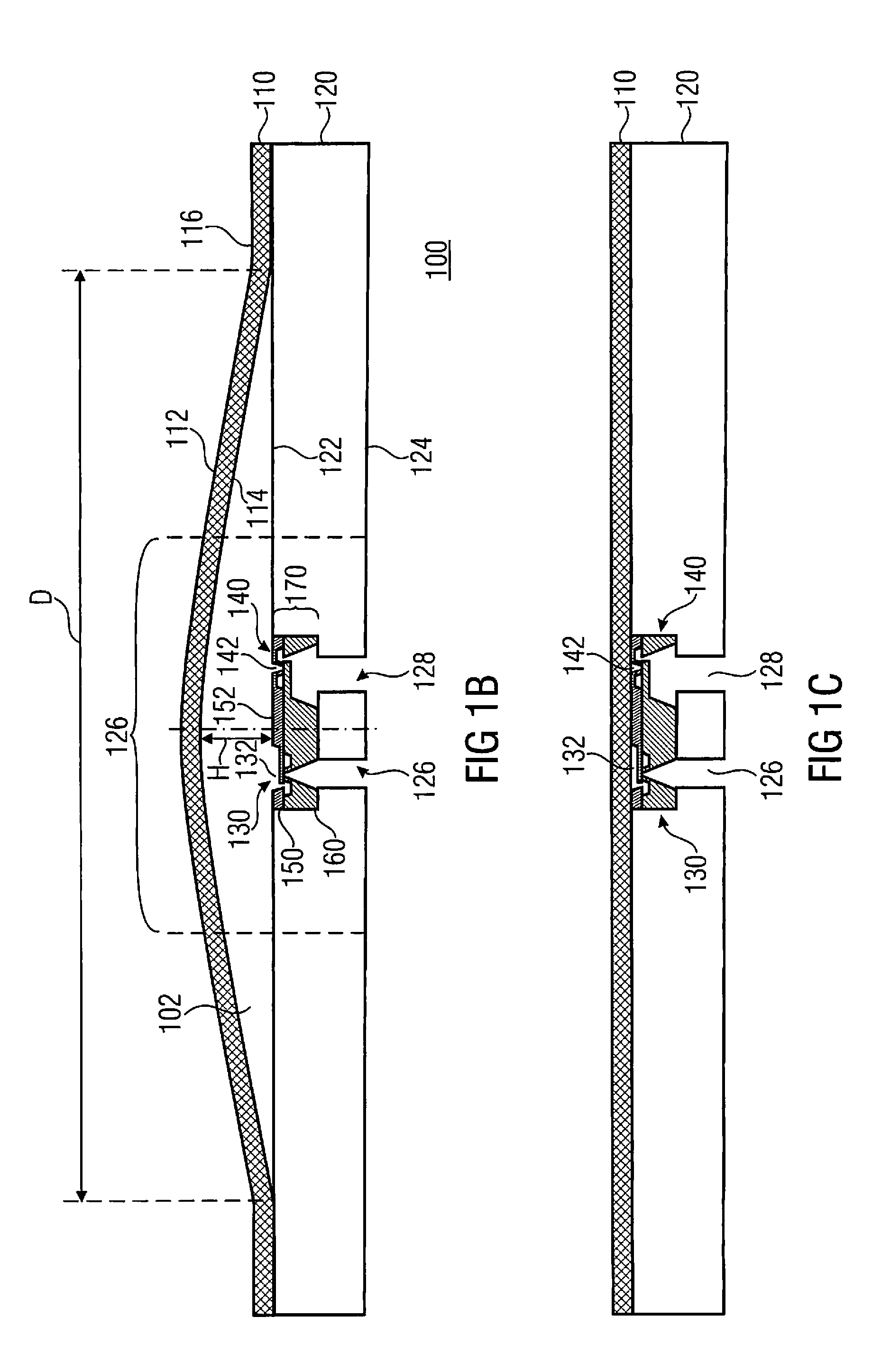
[0068]FIG. 1A shows a flow chart of an embodiment of a method for manufacturing a bending transducer comprising a drive means and a membrane. In step 1010 the membrane and the drive means are provided. In step 1020 a production signal is applied to the drive means during the bonding of the drive means to the membrane such that the drive means is pre-stressed after the bonding, wherein the production signal is of a same kind of signal as an operation signal to operate the bending transducer. In other words, the production signal is of the same kind of signal as the operation signal applied to the drive means during the normal operation of the bending transducer to bend or deflect the bending transducer and membrane.

[0069]The production signal is advantageously only released after the bonding has been terminated or is applied during the whole bonding process.

[0070]The bonding itself can be performed by any suitable bonding technology. The bonding of the drive means to the membrane can...


PUM

PropertyMeasurementUnit
Electric potential / voltageaaaaaaaaaa
Temperature coefficient of refractive indexaaaaaaaaaa
Compression ratioaaaaaaaaaa

Abstract

A method of manufacturing a bending transducer having a drive element and a membrane includes providing the membrane and the drive element and applying a production signal to the drive element during a bonding of the drive element to the membrane such that the drive element is pre-stressed after the bonding, wherein the production signal is of a same kind as an operation signal to operate the bending transducer.

Description

CROSS-REFERENCE TO RELATED APPLICATIONS[0001]This application is a continuation of copending International Application No. PCT / EP2010 / 052858, filed Mar. 5, 2010, which is incorporated herein by reference in its entirety.BACKGROUND OF THE INVENTION[0002]The present invention relates to a method for manufacturing a bending transducer, a micro pump and a micro valve, and to a micro pump and a micro valve comprising the bending transducer manufactured according to the method.[0003]According to conventional technology a large number of different micro membrane pumps exist, the drive concepts used being electromagnetic, thermal and piezoelectric driving principles. However, almost all of the micro membrane pumps available on the market are driven by piezoelectric driving principles.[0004]The compression ratio of micro pumps is an important parameter that defines the bubble tolerance and the counter pressure capability of the micro pumps when gasses are the media to be pumped. As also for ...

Claims


Application Information

Patent Timeline
IPC IPC(8): F04B45/04B23P15/00
CPCF04B43/043F16K99/0001F16K99/0015Y10T29/49236F16K2099/008F16K2099/0094H01L41/0973F16K99/0048F16K99/0057H10N30/2048H10N30/073H10N30/2047
Inventor HERZ, MARKUSRICHTER, MARTINWACKERLE, MARTIN
Owner FRAUNHOFER GESELLSCHAFT ZUR FOERDERUNG DER ANGEWANDTEN FORSCHUNG EV
Why Eureka
Try Eureka