Adjustable air flow bypass in a water vapor transfer assembly to reduce beginning of life water transfer variation

a technology of water vapor transfer and air flow bypass, which is applied in the direction of water supply installation, separation process, electrochemical generator, etc., can solve the problems of undesirable wvt assembly undesirable wvt assembly waste, etc., to minimize bol performance variation and minimize flow bypass

Inactive Publication Date: 2013-03-07
GM GLOBAL TECH OPERATIONS LLC
View PDF11 Cites 2 Cited by
  • Summary
  • Abstract
  • Description
  • Claims
  • Application Information

AI Technical Summary

Benefits of technology

[0010]In concordance with the instant disclosure, a WVT assembly that provides an ability to tune a BOL water transfer rate at high flows, and minimize BOL performance variation to permit for additional allowable water transfer rate degradation over the lifetime of the WVT assembly, minimizes flow bypass at low flows that would otherwise create poor idle performance, and can be packaged within an existing WVT housing, is surprisingly discovered.

Problems solved by technology

It is known that a water transfer rate of the WVT assembly degrades over the lifetime of the WVT assembly.
Due to performance variation between different WVT assemblies, certain ones of the different WVT assemblies may undesirably be closer to the EOL water transfer rate than other ones of the different WVT assemblies at BOL.
However, the masking is undesirably wasteful since an entirety of the WVT assembly is not being utilized.
However, actively controlled bypass valves add significant complexity to the fuel cell system, in addition to requiring significant packaging volume for the associated valve and manifolding.

Method used


Image

  • Adjustable air flow bypass in a water vapor transfer assembly to reduce beginning of life water transfer variation
  • Adjustable air flow bypass in a water vapor transfer assembly to reduce beginning of life water transfer variation
  • Adjustable air flow bypass in a water vapor transfer assembly to reduce beginning of life water transfer variation

Examples


Embodiment Construction

[0020]The following detailed description and appended drawings describe and illustrate various embodiments of the invention. The description and drawings serve to enable one skilled in the art to make and use the invention, and are not intended to limit the scope of the invention in any manner. In respect of the methods disclosed, the steps presented are exemplary in nature, and thus, the order of the steps is not necessary or critical.

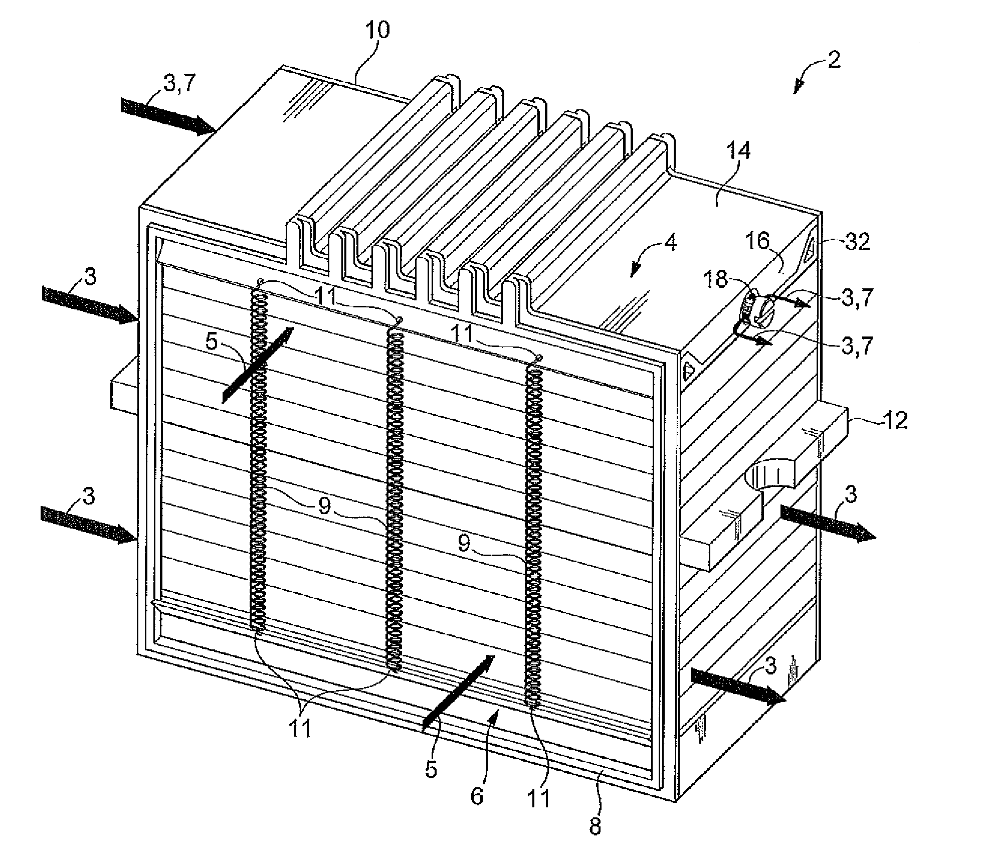
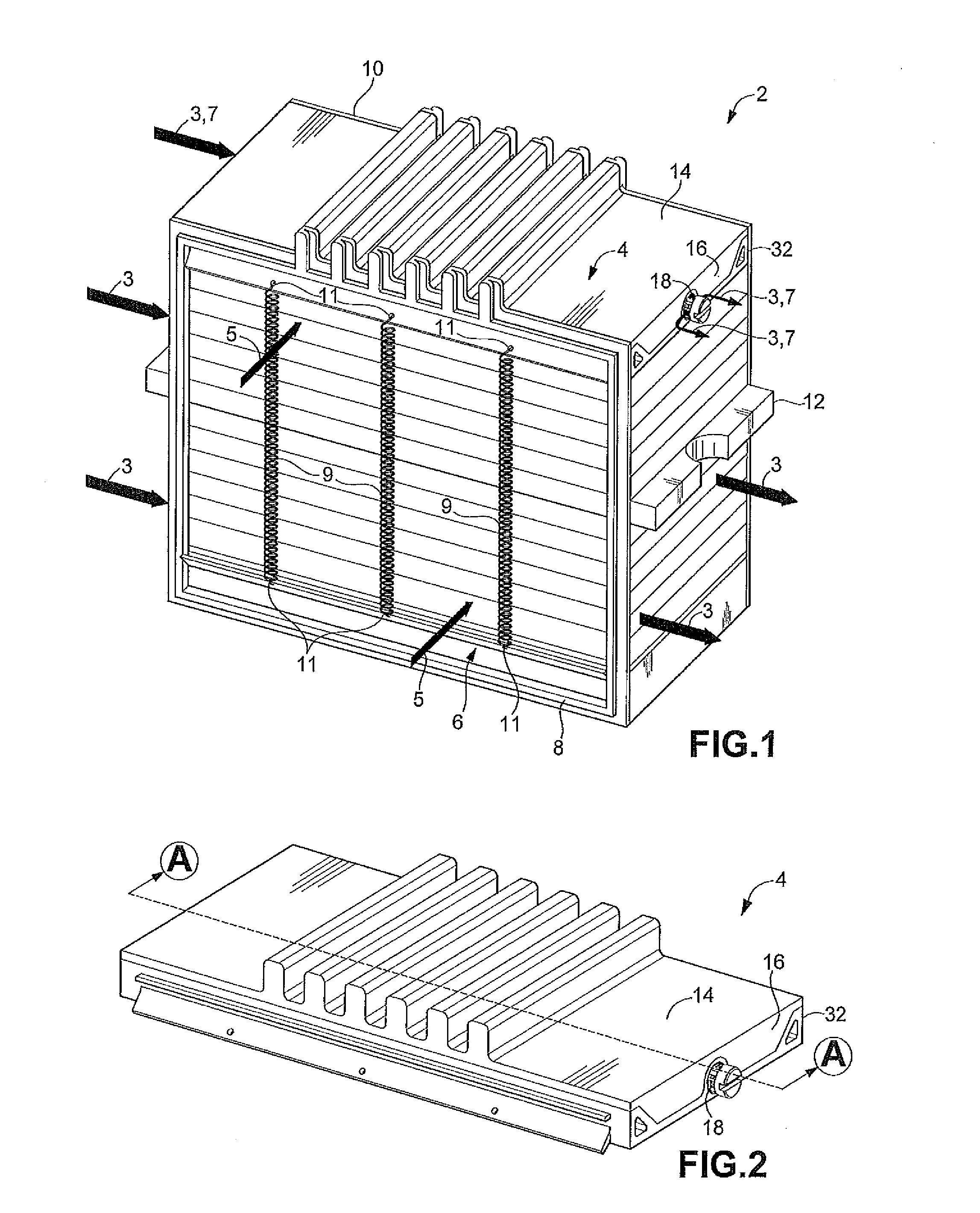
[0021]As shown in FIGS. 1-4, a water vapor transfer assembly 2 includes a plurality of wet plates configured to receive a wet stream 3, and a plurality of dry plates configured to receive a dry stream 5. The wet plates and the dry plates alternate in a stack and are separated from one another by water transfer membranes. The water vapor transfer assembly 2 permits a transfer of water from the wet stream 3 to the dry stream 5 during an operation of the water vapor transfer assembly 2. An exemplary water vapor transfer assembly is described in U.S. Pat....


PUM

PropertyMeasurementUnit
threshold flow rateaaaaaaaaaa
relative humidityaaaaaaaaaa
flow ratesaaaaaaaaaa

Abstract

A bypass unit for a water vapor transfer assembly includes a main body, a check valve, and an adjustable flow regulator. The main body has a conduit formed therethrough. The check valve is in communication with the conduit. The check valve normally militates against a flow of a bypass stream through the conduit and permits the flow of the bypass stream through the conduit above a threshold flow rate. The flow regulator is in communication with the conduit. The flow regulator permits an adjustment of the flow of the bypass stream to modify the water transfer rate of the water transfer assembly.

Description

FIELD OF THE INVENTION[0001]The present disclosure relates to a water vapor transfer assembly and, more particularly, to a water vapor transfer assembly for a fuel cell system.BACKGROUND OF THE INVENTION[0002]A fuel cell system is increasingly being used as a power source in a wide variety of applications. The fuel cell system has been proposed for use in vehicles as a replacement for internal combustion engines, for example. The fuel cell system may also be used as a stationary electric power plant in buildings and residences, portable power in video cameras, computers, and the like. Typically, the fuel cell system includes a plurality of fuel cells arranged in a fuel cell stack to generate electricity, which is used to charge batteries or provide power to an electric motor.[0003]A typical fuel cell is known as a polymer electrolyte membrane (PEM) fuel cell, which combines a fuel such as hydrogen and an oxidant such as oxygen to produce electricity and water. The oxygen is generall...

Claims


Application Information

Patent Timeline
Patent Type & Authority Applications(United States)
IPC IPC(8): F15D1/00F16K15/00
CPCY02E60/50H01M8/04776H01M8/04171H01M8/04141Y10T137/0324Y10T137/7837
Inventor MARTINCHEK, DAVID A.BRONCHETTI, THOMAS D.JERMY, IAN R.
Owner GM GLOBAL TECH OPERATIONS LLC
Why Eureka
Try Eureka