Muffler for an exhaust system of vehicle

a technology for exhaust systems and mufflers, which is applied in the direction of engines, mechanical apparatus, machines/engines, etc., can solve the problems of deterioration of surrounding components, loss of attenuation functions of mufflers, and often caused by external corrosion, so as to prevent deterioration of peripheral components, improve fuel efficiency, and prevent function loss

Inactive Publication Date: 2013-03-07
HYUNDAI MOTOR CO LTD +1
View PDF4 Cites 5 Cited by
  • Summary
  • Abstract
  • Description
  • Claims
  • Application Information

AI Technical Summary

Benefits of technology

[0010]The present invention provides a noise tunable muffler for an exhaust system of a vehicle, which prevents deterioration of peripheral components due to high temperature exhaust gas, prevents loss of function due to external corrosion, and improves fuel efficiency through weight reduction.

Problems solved by technology

Stainless steel has high thermal conductivity, thus, the high temperature of the exhaust gas is transferred to the component surrounding the muffler (such as a lower vehicle body, fuel tank, etc.) via convection, radiation, or conduction, thereby causing deterioration of the surrounding components as a result.
Moreover, despite the use of stainless steel materials, external corrosion is often caused by the high temperature exhaust gas and by external corrosion promoting substances such as salt water created from deicing salt used in the winter, etc.
Furthermore, perforation corrosion is caused by condensation water, which leads to loss of the attenuation functions of the muffler, thereby rendering the muffler unaffected.
These types of mufflers are effective in reducing high-frequency noise but are ineffective to low-frequency noise.
In particular, the noise tuning corresponding to the vibration frequency (Hz) of the engine and the engine rpm is limited.
Moreover, a large amount of expensive glass fibers must be used as insulating and sound absorbing materials.
Additionally, the glass fibers may cause various problems such as deterioration of assemblability, environmental pollution, difficulties in mass production, etc.
Furthermore, plastic mufflers have a structure in which the exhaust gas is in direct contact with the plastic casing, and thus the plastic casing may melt while vehicle running.

Method used

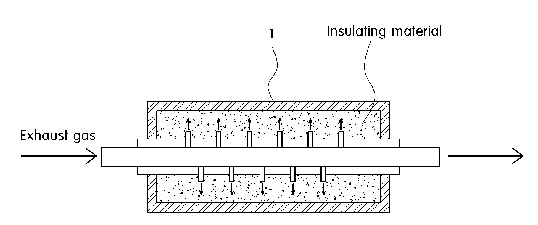
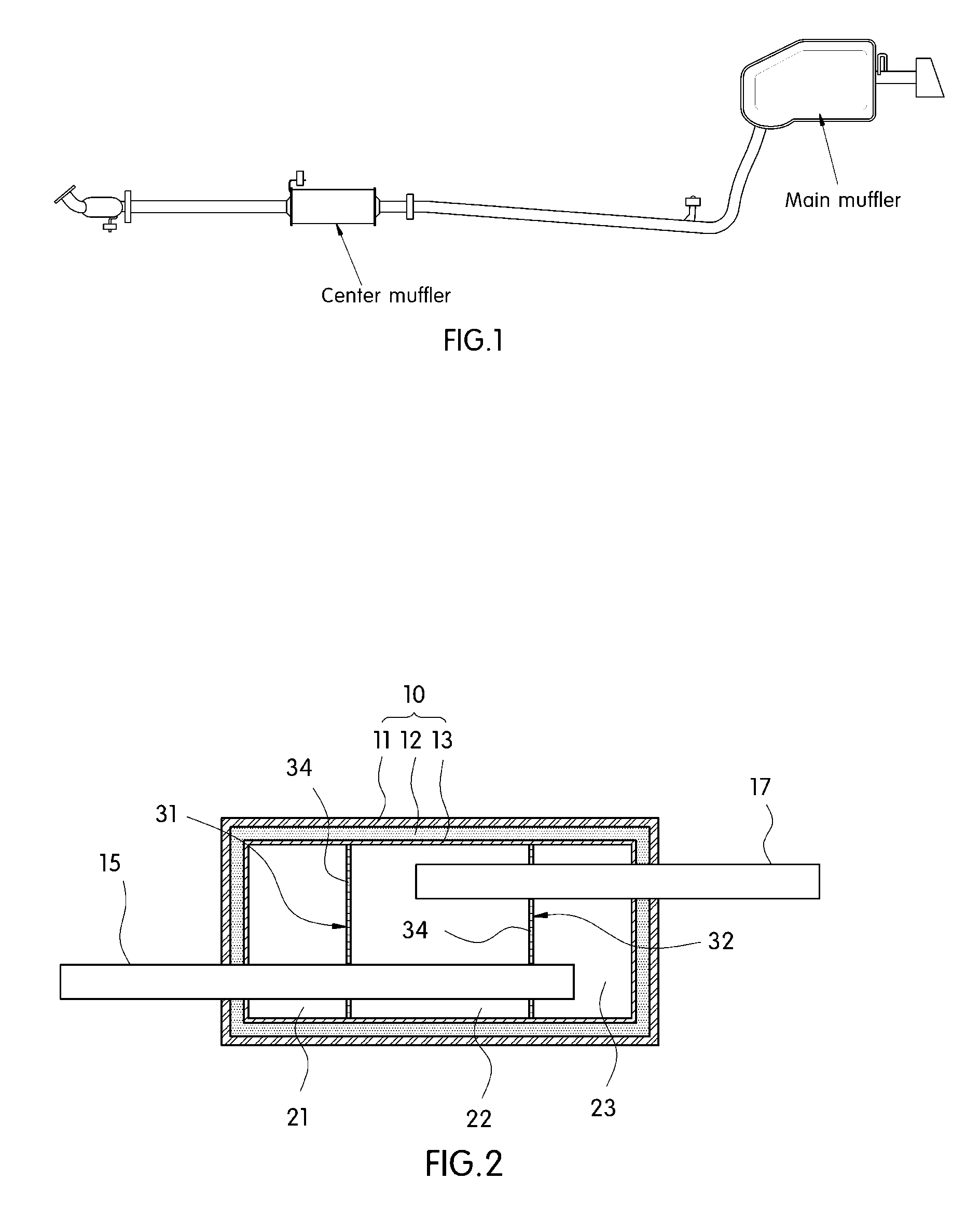
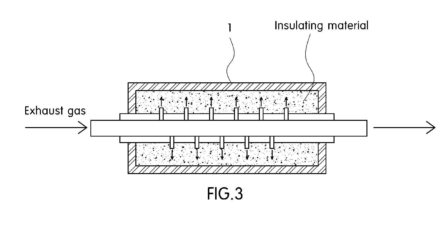

Image

  • Muffler for an exhaust system of vehicle
  • Muffler for an exhaust system of vehicle
  • Muffler for an exhaust system of vehicle

Examples


Embodiment Construction

[0035]Hereinafter reference will now be made in detail to various embodiments of the present invention, examples of which are illustrated in the accompanying drawings and described below. While the invention will be described in conjunction with exemplary embodiments, it will be understood that present description is not intended to limit the invention to those exemplary embodiments. On the contrary, the invention is intended to cover not only the exemplary embodiments, but also various alternatives, modifications, equivalents and other embodiments, which may be included within the spirit and scope of the invention as defined by the appended claims.

[0036]It is understood that the term “vehicle” or “vehicular” or other similar term as used herein is inclusive of motor vehicles in general such as passenger automobiles including sports utility vehicles (SUV), buses, trucks, various commercial vehicles, watercraft including a variety of boats and ships, aircraft, and the like, and inclu...


PUM


Abstract

Disclosed is a muffler for an exhaust system of a vehicle, which improves fuel efficiency through weight reduction and reduces deterioration of peripheral components. To this end, the present provides a muffler for an exhaust system of a vehicle. More specifically, the muffler includes a triple-material hollow casing, in which an outer layer formed of a plastic material and disposed on the outermost surface of the muffler, an intermediate insulating layer disposed on the inside of the outer layer and containing an aerogel material, and an inner layer formed of a stainless steel material and disposed on the inside of the intermediate insulating layer are stacked.

Description

CROSS-REFERENCE TO RELATED APPLICATION[0001]This application claims under 35 U.S.C. §119(a) the benefit of Korean Patent Application No. 10-2011-0088536 filed Sep. 1, 2011, the entire contents of which are incorporated herein by reference.BACKGROUND[0002](a) Technical Field[0003]The present disclosure relates to a muffler for an exhaust system of a vehicle. More particularly, it relates to a muffler for an exhaust system of a vehicle, which can improve fuel efficiency through weight reduction and reduced deterioration of peripheral components.[0004](b) Background Art[0005]Mufflers are typically installed along the exhaust line as part of the exhaust system of an internal combustion engine or any engine of a motorized vehicle. The muffler reduces exhaust noise through absorption techniques. In particular, the engine exhaust is routed through a series of passages and chambers lined typically with roving fiberglass wool and / or resonating chambers tuned to cause reflected waves that int...

Claims


Application Information

Patent Timeline
Patent Type & Authority Applications(United States)
IPC IPC(8): F01N13/08
CPCF01N13/02F01N1/10F01N13/16F01N13/148F01N13/14
Inventor CHOI, MIN HO
Owner HYUNDAI MOTOR CO LTD
Why Eureka
Try Eureka