Method and apparatus for adaptive scatter correction

a scatter correction and adaptive technology, applied in the field of diagnostic imaging, can solve the problems of limiting performance, increasing spr degrade image quality, and increasing scatter, and achieve the effect of improving the scatter correction for ct imaging

Active Publication Date: 2013-03-07
GENERAL ELECTRIC CO
View PDF7 Cites 10 Cited by
  • Summary
  • Abstract
  • Description
  • Claims
  • Application Information

AI Technical Summary

Benefits of technology

[0012]Therefore, it would be desirable to design an apparatu

Problems solved by technology

As CT systems have grown in z-coverage (i.e., increased numbers of slices), however, scatter has become an increasingly significant factor.
It is well-known that an increased SPR degrades image quality due to image artifact and contrast loss.
However, such solutions tend to be expensive, may limit performance, and may increase an amount of dose required to obtain adequate image data.
Such solutions may be computationally attractive, but may have limitations that are exacerbated in wider z-coverage and low energy applications.
Typically, such solutions are not accurate for no

Method used


Image

  • Method and apparatus for adaptive scatter correction
  • Method and apparatus for adaptive scatter correction
  • Method and apparatus for adaptive scatter correction

Examples


Embodiment Construction

[0028]The operating environment of the invention is described with respect to a sixty-four-slice computed tomography (CT) system. However, it will be appreciated by those skilled in the art that the invention is equally applicable for use with other multi-slice configurations. Moreover, the invention will be described with respect to the detection and conversion of x-rays. However, one skilled in the art will further appreciate that the invention is equally applicable for the detection and conversion of other high frequency electromagnetic energy. The invention will be described with respect to a “third generation” CT scanner, but is equally applicable with other CT systems.

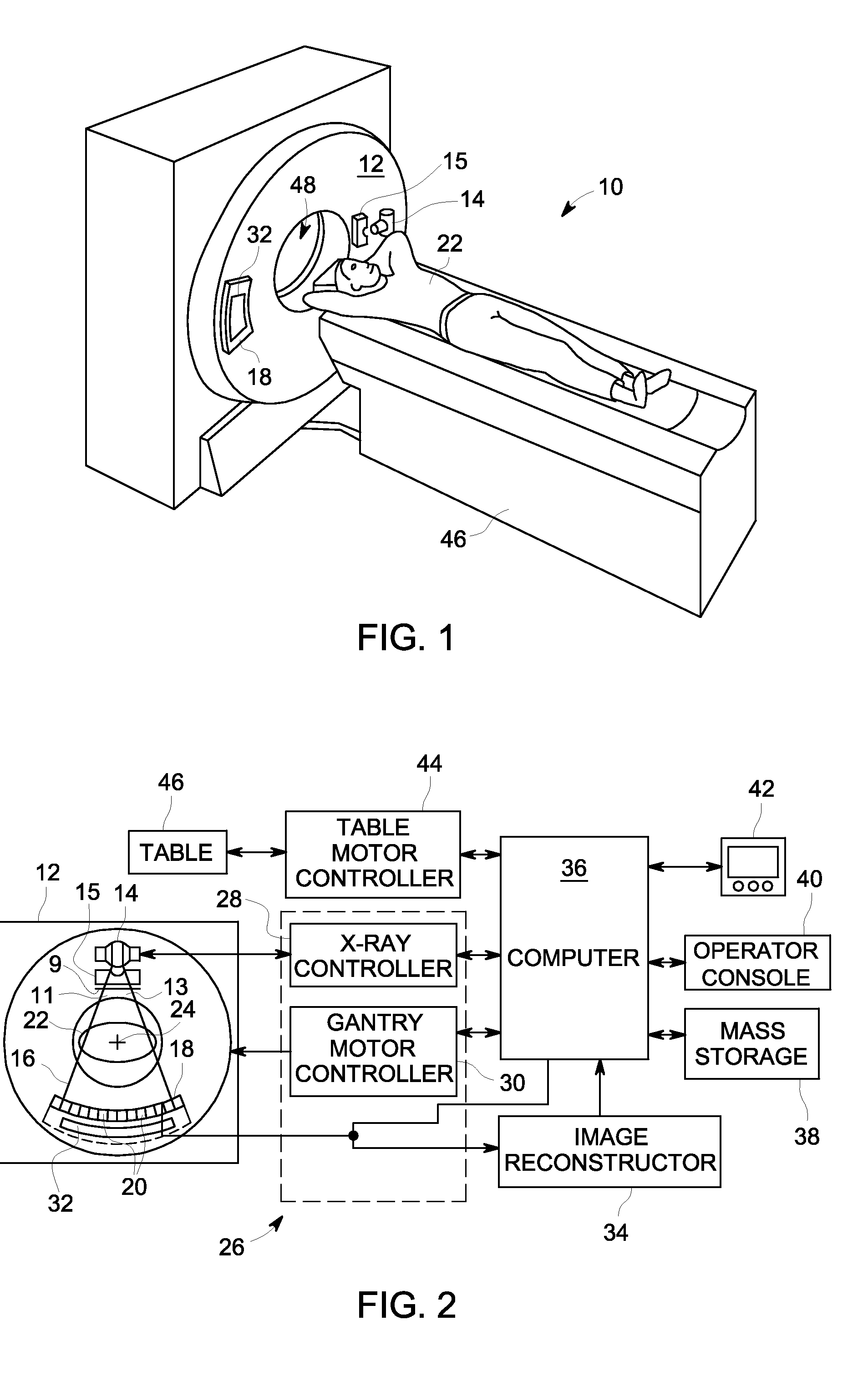
[0029]Referring to FIGS. 1 and 2, a computed tomography (CT) imaging system 10 is shown as including a gantry 12 representative of a “third generation” CT scanner. Gantry 12 has an x-ray source 14 that projects a beam of x-rays through a bowtie filter 15 and toward a detector assembly or collimator 18 on the oppo...


PUM


Abstract

A CT system includes a rotatable gantry having an opening to receive an object to be scanned, an x-ray source configured to project an x-ray beam toward the object having a primary intensity, a detector configured to detect high frequency electromagnetic energy passing through the object and output imaging data, and a data acquisition system (DAS) connected to the detector and configured to receive the imaging data. The system also includes a computer programmed to obtain image projection data of the object from the DAS, correct the projection data using a scatter function that is based at least on a known characteristic of the x-ray beam, and generate images using the corrected projection data.

Description

BACKGROUND OF THE INVENTION[0001]Embodiments of the invention relate generally to diagnostic imaging and, more particularly, to a method and apparatus for adaptive scatter correction in an imaging system.[0002]Typically, in computed tomography (CT) imaging systems, an x-ray source emits a fan-shaped beam toward a subject or object, such as a patient or a piece of luggage. Hereinafter, the terms “subject” and “object” shall include anything capable of being imaged. The beam, after being attenuated by the subject, impinges upon an array of radiation detectors. The intensity of the attenuated beam radiation received at the detector array is typically dependent upon the attenuation of the x-ray beam by the subject. Each detector element of the detector array produces a separate electrical signal indicative of the attenuated beam received by each detector element. The electrical signals are transmitted to a data processing system for analysis which ultimately produces an image.[0003]Gene...

Claims


Application Information

Patent Timeline
IPC IPC(8): A61B6/03
CPCA61B6/032A61B6/5282A61B6/482
Inventor LIU, XINHSIEH, JIANGWU, XIAOYE
Owner GENERAL ELECTRIC CO
Why Eureka
Try Eureka