
Flue gas air preheater, and a method for installation, as well as an air pipe component for a flue gas air preheater

a flue gas air preheater and air pipe component technology, which is applied in indirect heat exchangers, manufacturing tools, light and heating apparatus, etc., can solve the problems of weak corrosion of the cold heat exchanger structure, the joint between the coldest air pipe and the end plate connected to it may be corroded, and the air supply to the air pipe has not yet been substantially warmed. , to achieve the effect of reducing the turbulence of air flow, facilitating the replacement of the air pip

Inactive Publication Date: 2013-03-14
VALMET TECH OY
View PDF12 Cites 14 Cited by
  • Summary
  • Abstract
  • Description
  • Claims
  • Application Information

AI Technical Summary

Benefits of technology

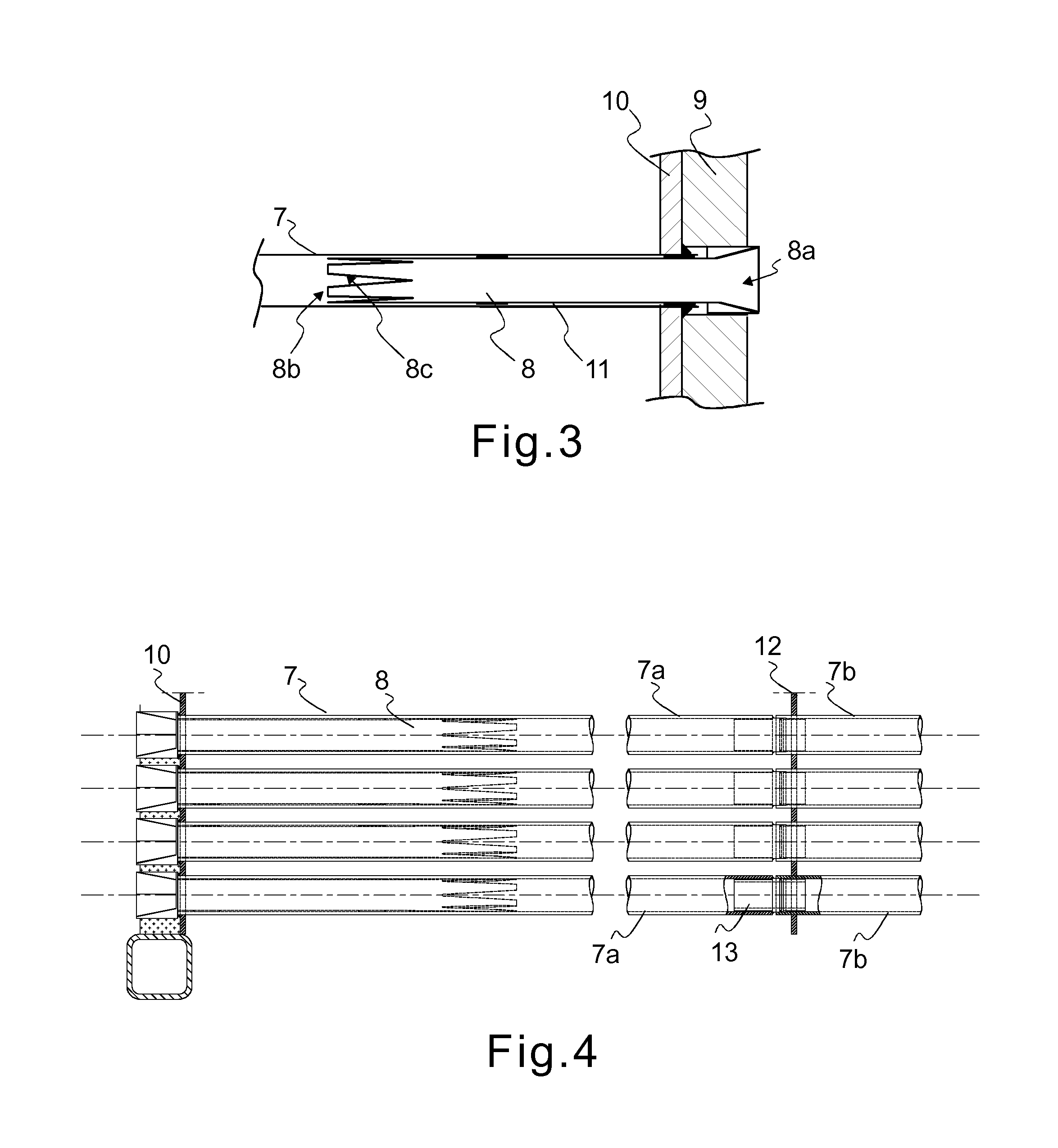
The present invention relates to a new way of replacing air pipes in LUVO blocks used in industrial plants. The advantage of this solution is that only a portion of the air pipes need to be replaced, instead of the entire block. The new and old air pipes are joined together using conical fittings, and a fastening sleeve is used to secure the two together. The air guide sleeve is inserted at the initial end of the air pipe to reduce turbulence and the sleepe is made of a poorly heat conductive material to equalize the temperature over a longer distance. This new method makes replacing air pipes faster, easier, and allows for better testing of materials.

Problems solved by technology

Furthermore, the air supplied to the air pipe has not yet been substantially warmed at the initial end of the air pipe.
Reaching the acid dew point, in turn, causes strong corrosion in the cold heat exchanger structure because of condensed water and sulphuric acid, and eroding through in a short time, particularly with difficult fuels.
In particular, the joint between the coldest air pipe and the end plate connected to it may be corroded, if the temperature of the material is too low.
It is obvious that the replacement and repair of the whole LUVO block will cause a long downtime of the boiler, and the work cannot be done in connection with other, shorter interruptions in operation.

Method used


Image

  • Flue gas air preheater, and a method for installation, as well as an air pipe component for a flue gas air preheater
  • Flue gas air preheater, and a method for installation, as well as an air pipe component for a flue gas air preheater
  • Flue gas air preheater, and a method for installation, as well as an air pipe component for a flue gas air preheater

Examples


Embodiment Construction

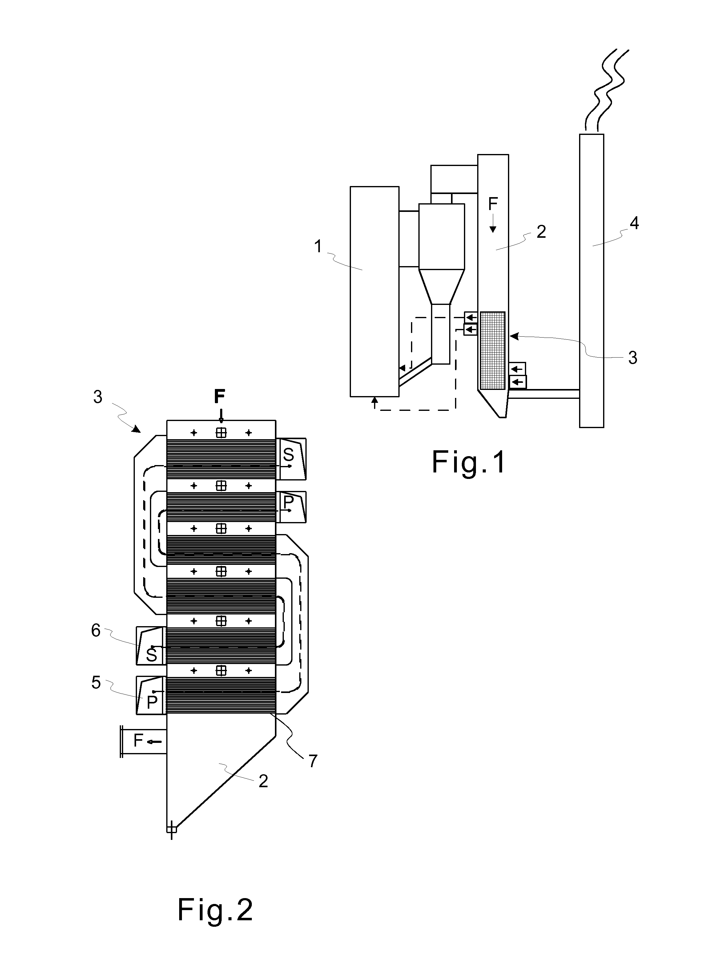
[0028]FIG. 1 shows, in a principle view, a system for producing and utilizing thermal energy, for example a boiler, that makes use of combustion of solid fuel. The system comprises a furnace 1, in which the combustion of the fuel takes place, a flue gas duct 2, to which the flue gases formed in the combustion are led, a flue gas air preheater 3, by which the combustion air used in the combustion is heated before it is introduced in the furnace, and a stack 4. The preheater 3 is placed in the flue gas duct 2. As can be seen from the figure, the preheater 3 is placed at the terminal end of the flue gas duct 2 in the flow direction F of the flue gases.

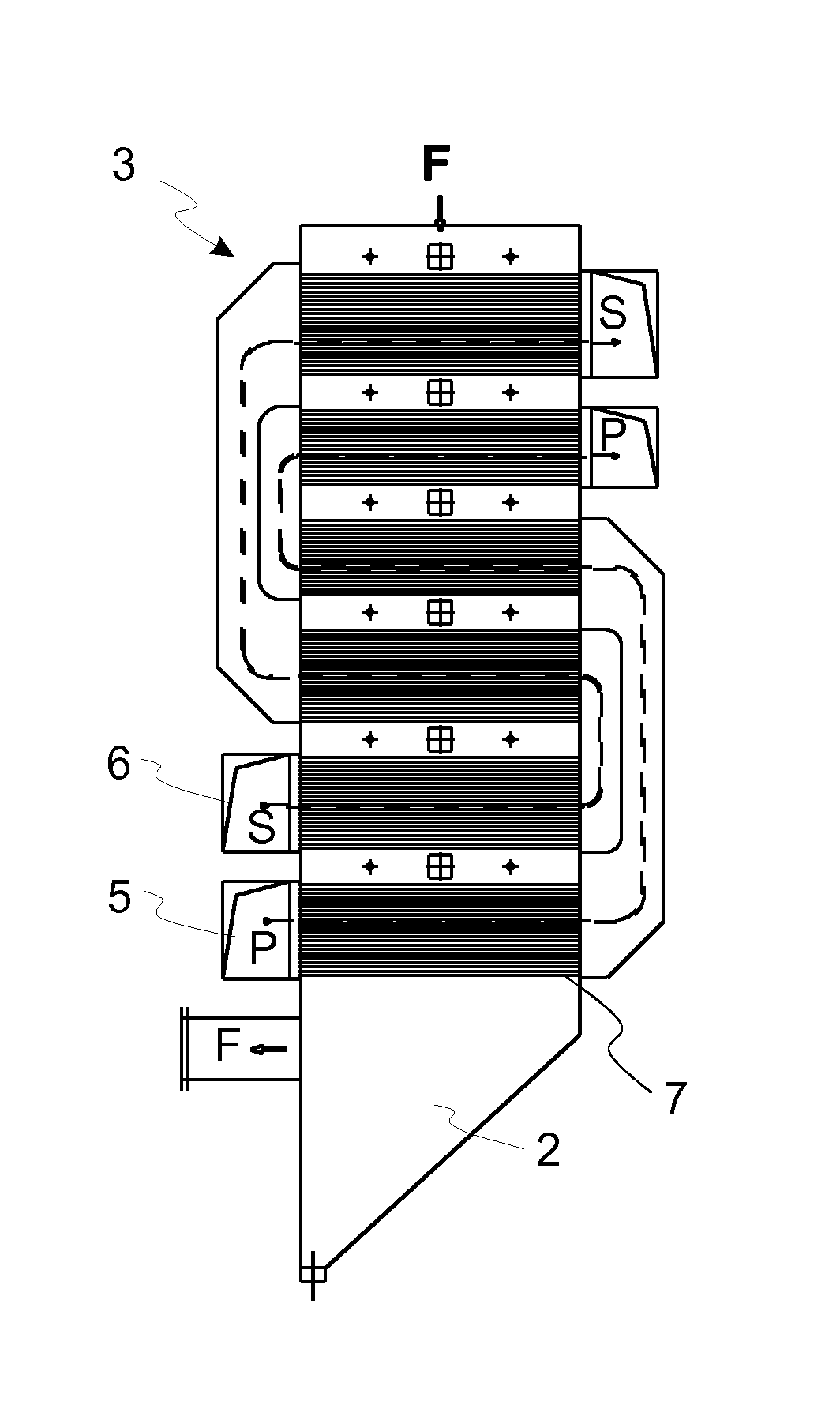
[0029]FIG. 2 shows an embodiment of the preheater 3 in more detail. In this example, the air flows S, P to be heated are guided into the preheater 3 from air supply areas 5, 6 in the lower part. The heated air is discharged from the upper part of the preheater 3. In the example, the preheater 3 comprises two air circulations, i.e. a prima...


PUM

PropertyMeasurementUnit
lengthaaaaaaaaaa
weightaaaaaaaaaa
total weightaaaaaaaaaa

Abstract

A flue gas air preheater and a method for the installation of air pipes for a flue gas air preheater. The method includes cutting an air pipe connected to the preheater and detaching the portion of the air pipe that is to be removed from the preheater for replacement; fitting a separate new air pipe in place of the air pipe portion to be removed; and connecting the new air pipe to the remaining portion of the air pipe in a sealed manner. The fixing may be performed utilizing a fastening sleeve fixed to the end of the new air pipe and inserting it in the remaining portion of the air pipe. The fixing may be performed by a mechanical sealing solution without welding. The air pipe component for the flue gas air preheater includes an air pipe, and a fastening sleeve.

Description

FIELD OF THE INVENTION[0001]The invention relates to a method for the installation of air pipes of a flue gas air preheater. Furthermore, the invention relates to a flue gas air preheater. The invention also relates to an air pipe component for a flue gas air preheater.BACKGROUND OF THE INVENTION[0002]For preheating combustion air for a large solid fuel boiler, flue gas air pre-heaters (German Luftvorwärmer, LUVO) are typically used, in which the heating medium, i.e. flue gas, flows outside heat exchanger pipes, and the medium to be heated, i.e. air, flows inside the heat exchanger pipes. The heat exchanger pipes, which are also called air pipes in this description, are typically placed horizontally in the flue gas duct, and a large number of heat exchanger pipes constitutes a heat exchanger unit. Heat exchanger units on different height levels are connected to each other by air ducts placed outside the flue gas duct. There are also configurations, in which the flue gas flows inside...

Claims


Application Information

Patent Timeline
Patent Type & Authority Applications(United States)
IPC IPC(8): F28F1/00B23P11/00
CPCF28D7/1607F28D21/001Y10T29/4973F28F2275/00F28F11/00Y02E20/34F23L15/04
Inventor NICKULL, JANKAINU, VESA
Owner VALMET TECH OY
Learn More