
Microwave cavity with dielectric region and method thereof

a dielectric region and microwave cavity technology, applied in the direction of resistance/reactance/impedence, instruments, measurement devices, etc., can solve the problems of prohibitively large mode and significant limitations of the disclosed system, and achieve the effect of reducing the diameter of the microwave beam and reducing the size of the resonator

Inactive Publication Date: 2013-03-14
ARMY US SEC THE THE
View PDF5 Cites 18 Cited by
  • Summary
  • Abstract
  • Description
  • Claims
  • Application Information

AI Technical Summary

Benefits of technology

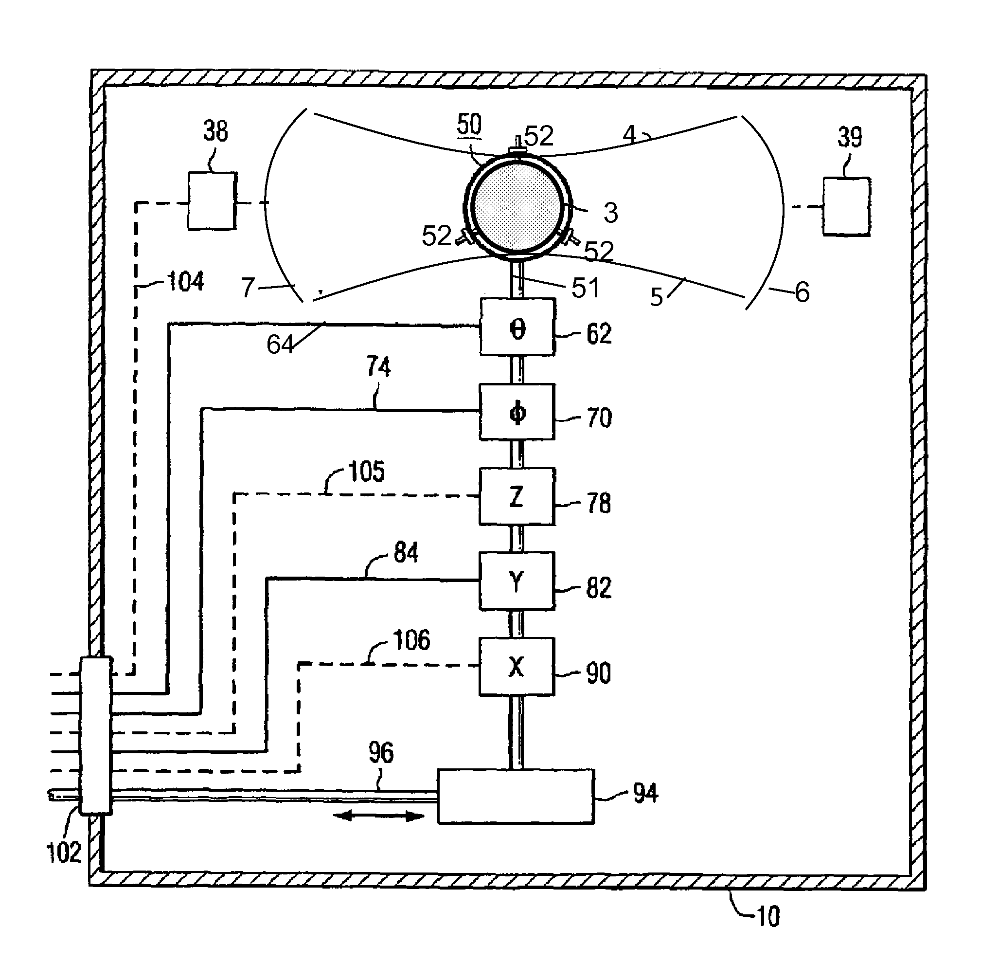
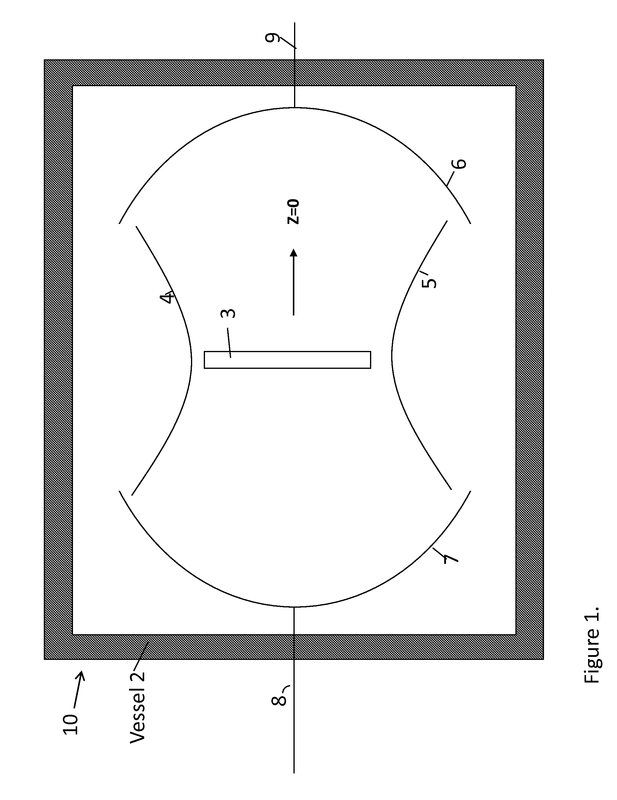
This patent text describes a way to improve microwave measurements in an open confocal cavity resonator. By replacing the air or vacuum in the resonator with a dielectric material of relatively high dielectric constant, the size of the resonator can be reduced while maintaining an adequate Q-value. This change also allows for smaller samples to be measured because the higher dielectric constant decreases the diameter of the microwave beam at the region where the sample is placed.

Problems solved by technology

However, the disclosed system has some significant limitations.
The lower frequency limit (cut-off) due to physical constraints of the cavity and sample size is limited by cross-sectional area of the microwave mode supported by the cavity, the mode becoming prohibitively large at lower frequencies.

Method used


Image

  • Microwave cavity with dielectric region and method thereof
  • Microwave cavity with dielectric region and method thereof
  • Microwave cavity with dielectric region and method thereof

Examples


Embodiment Construction

[0014]The present invention now will be described more fully hereinafter with reference to the accompanying drawings, in which embodiments of the invention are shown. However, this invention should not be construed as limited to the embodiments set forth herein. Rather, these embodiments are provided so that this disclosure will be thorough and complete, and will fully convey the scope of the invention to those skilled in the art. In the drawings, the thickness of layers and regions may be exaggerated for clarity. Like numbers refer to like elements throughout. As used herein the term “and / or” includes any and all combinations of one or more of the associated listed items.

[0015]As used herein, the singular forms “a”, “an” and “the” are intended to include the plural forms as well, unless the context clearly indicates otherwise. It will be further understood that the terms “comprises” and / or “comprising,” when used in this specification, specify the presence of stated features, integ...


PUM


Abstract

A method and apparatus for obtaining dielectric constant and other measurements of a sample, comprising an open cavity resonator; a microwave energy generator for creating a resonating microwave in the open cavity resonator; a predetermined dielectric material having a high dielectric constant in the range of 2 to 100,000 substantially filling the region in which a microwave resonates; the dielectric material adapted to receive a sample for measurement of the dielectric properties of the sample; whereby during operation the resonating microwave beam is substantially immersed in the predetermined dielectric material such that the effective electrical spot size and beam cross-section along the cylindrical axis of the resonating microwave is reduced as a function of the inverse of the square root of the predetermined dielectric material dielectric constant. The dielectric constant or loss tangent of the sample may be determined based upon the change in the cavity's resonant frequency modes.

Description

GOVERNMENT INTEREST[0001]The invention described herein may be manufactured, used, and / or licensed by or for the United States Government.BACKGROUND OF THE INVENTION[0002]Accurate determination of microwave material permittivity and loss factor over the entire microwave regime and over the desired temperature range of operation are needed for accurate design, operation and evaluation of microwave components, circuits, antenna and systems. Microwave engineers can input such precise material parameters into currently available software programs to accurately model devices as functions of temperature. In this way, the number of iterations and time required to develop components, circuits, subsystems and systems that operate to the specified performance level and over the specified temperature range of operation can be reduced. Such efficient development, rather than development by trial and error, will lower component, circuit, subsystem and system cost.[0003]U.S. Pat. No. 6,864,690, h...

Claims


Application Information

Patent Timeline
Patent Type & Authority Applications(United States)
IPC IPC(8): G01R27/04
CPCG01N22/00G01R27/2658
Inventor POTREPKA, DANIEL M.TIDROW, STEVEN C.
Owner ARMY US SEC THE THE
Learn More