Optical element and illuminant device using the same

a technology of optical elements and illuminant devices, applied in the field of optical elements, can solve the problem that the effect of saving energy cannot be achieved, and achieve the effect of enlarge the light-emitting angl

Active Publication Date: 2013-03-14
CHUN KUANG OPTICS CORP
View PDF5 Cites 15 Cited by
  • Summary
  • Abstract
  • Description
  • Claims
  • Application Information

AI Technical Summary

Benefits of technology

[0011]The optical element of the present invention uses the extending part which is extended from the circumference of the top surface to guide the light entered the optical element so that the light can be refracted by the extending part or reflected to the light-emitting surface and emitting from the light-emitting s

Problems solved by technology

However, the required power for driving the LEDs is increased when the number of

Method used


Image

  • Optical element and illuminant device using the same
  • Optical element and illuminant device using the same
  • Optical element and illuminant device using the same

Examples


Embodiment Construction

[0027]A preferred embodiment of the present invention will be described with reference to the drawings.

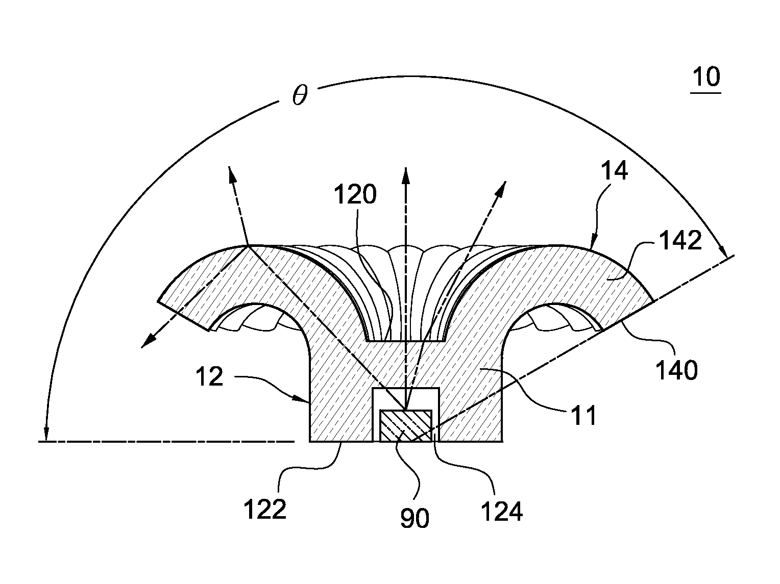
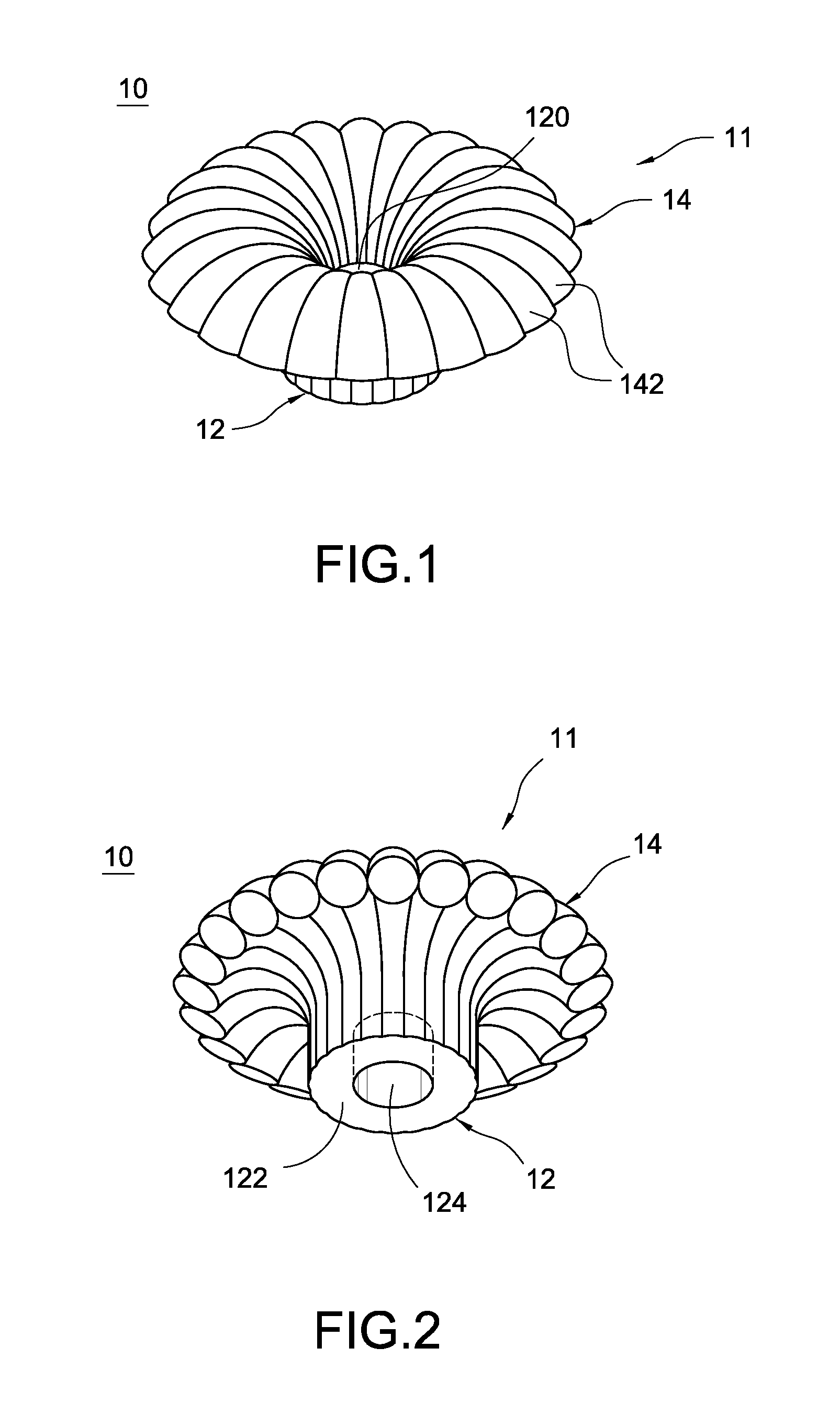
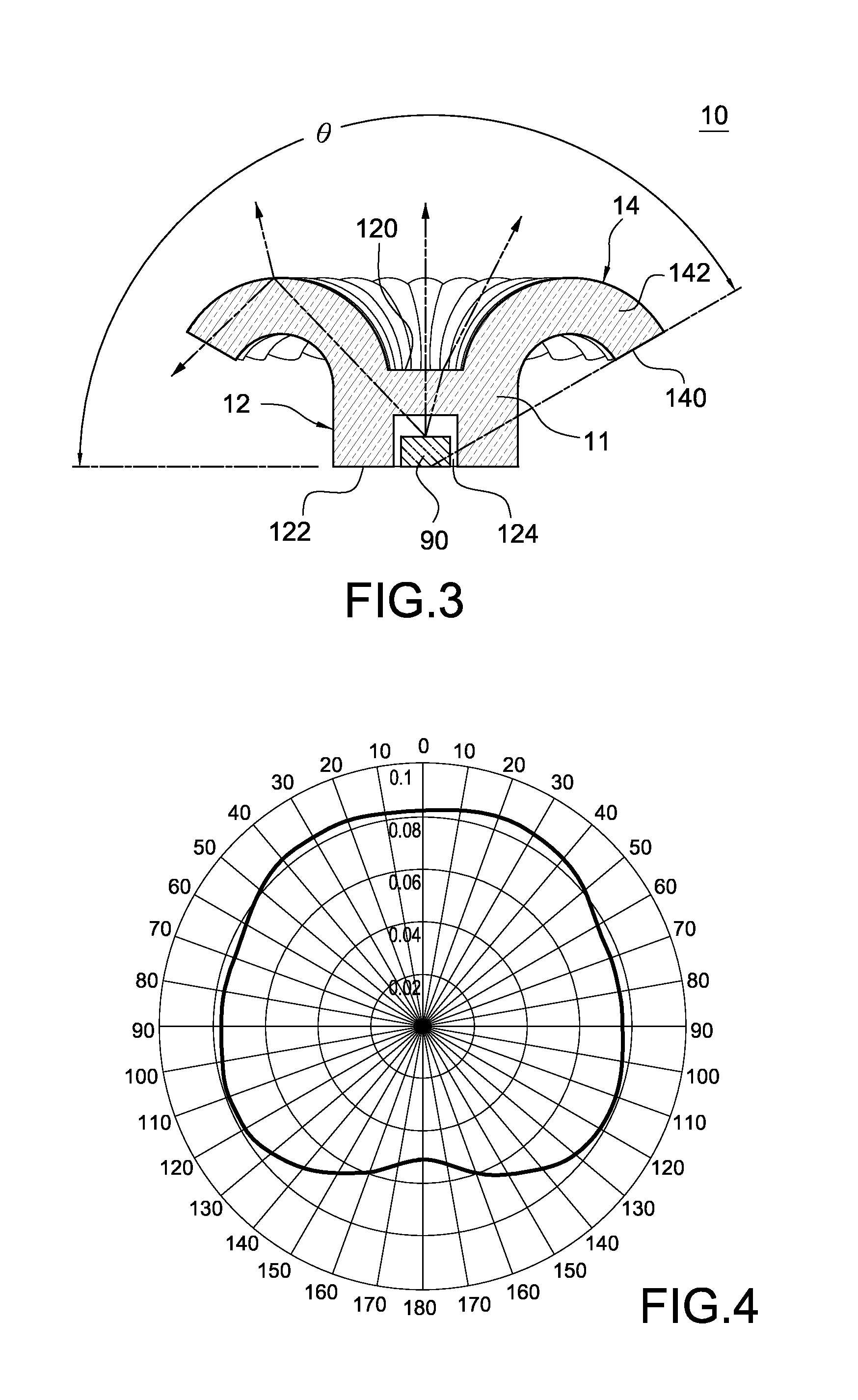
[0028]Reference is made to FIG. 1 and FIG. 2, which are perspective views of an optical element from different view angles according to a first preferred embodiment of the present invention. The optical element10 is applied for disposing on a light emitting diode (LED) 90 such that the luminous intensity distribution of light emitted by the LED can be changed and the emitting angle of the light can be enlarged. The LED 90 is, but not limited to, a LED chip, other equivalent elements can be used without departing from the scope of the present invention.

[0029]The optical element 10 can be integrally-formed by plastic, glass, silicon rubber, silicon resin or other light transparent material by injection molding. The optical element 10 has a transparent main body 11. The main body 11 includes a light guiding pillar 12 and an extending part 14. In this embodiment, the light guiding pill...


PUM


Abstract

An optical element is assembled to a light emitting diode (LED) to form an illuminative light source. The optical element includes a transparent main body having a light guiding pillar and an extending part. The light guiding pillar has a top surface and a bottom surface having a recess. The extending part is extended from the circumference of the top surface and an end of the extending part has at least a light-emitting surface. Wherein the LED is disposed on the recess and emits light to the optical element. The extending part guides the light and enlarges the light-emitting angle.

Description

BACKGROUND OF THE INVENTION[0001]1. Field of the Invention[0002]The present invention relates to an optical element, and in particular to an optical element which can enlarge light emitting angle of light.[0003]2. Description of Prior Art[0004]A light emitting diode (LED) is a kind of semiconductor device, which exploits the property of direct-bandgap semiconductor material to convert electric energy into light energy efficiently and has the advantages of long service time, high stability and low power consumption and is developed to replace the traditional non-directivity light tube and incandescent lamp.[0005]The LED is a point-like light source and has high directivity so that the lighting surface of the LED is narrower than that of the traditional light sources, and the luminous intensity of the LED is gradually reduced while the lighting distance is increased, so that the LED is more suitable for providing short-distance and small area lighting fixture, such as table lamp.[0006...

Claims


Application Information

Patent Timeline
IPC IPC(8): F21V8/00
CPCF21K9/52F21K9/135F21V3/00F21V29/85F21K9/232F21K9/61F21Y2115/10
Inventor HUANG, HSIN-CHIEHYEN, CHIA-SONGTENG, SHUN-WEN
Owner CHUN KUANG OPTICS CORP
Why Eureka
Try Eureka