Reformer apparatus and method

a reformer and apparatus technology, applied in the field of reformer apparatus and method, can solve the problems of low hydrocarbon conversion, complex control system comprising multiple control loops, and ineffective reforming on a smaller scale, and achieve the effect of optimizing the reforming conditions, cost-effectiveness, and high efficiency

Active Publication Date: 2008-05-29
MEGGIT (UK) LTD
View PDF24 Cites 23 Cited by
  • Summary
  • Abstract
  • Description
  • Claims
  • Application Information

AI Technical Summary

Benefits of technology

[0031]A passive stage-by-stage fuel distribution network suitable for use with low pressure fuel is incorporated, and the resistances within the fuel distribution network are tailored such that the amount of fuel delivered to each successive combustion stage diminishes in a predetermined and precise amount relative to the one before and the one after throughout the length of the reformer despite the fact that the pressure drop that drives the fuel flow increases. Because of this control of fuel distribution, and because the flows within the combustion and fuel passages are maintained in laminar (as opposed to turbulent) flow, the flows of the fuel and air at each stage remains relatively constant during severe “turn up” and “turn down” conditions. This system of stage-wise fuel distribution also eliminates the need for multiple control loops, and allows the operator effectively to control the entire reforming aspect of the system through monitoring and control of a very limited number of process variables.
[0032]The use of variable fuel addition to each stage, which allows for the tapering off of fuel addition to later stages, also limits the metal temperatures required in order to achieve a given and desired syngas temperature, thus providing optimized reforming conditions. High efficiency is achieved by capturing and utilizing the heat from the produced syngas in a multiple-steam heat exchanger to pre-heat the gases before entering the reforming process steps, and is also utilized to produce steam for use in the process.
[0033]The preferred process and apparatus of this invention is also effective to eliminate the conditions that would produce unwanted coking, and to localize the areas where conditions that can cause metal dusting occur, by controlling the temperature of the gases either above or below the temperature at which metal dusting occurs to very specific locations within the apparatus, which locations are outside of the heat exchangers, and reforming chambers, and which locations can be cost-effectively protected by use of materials that will not be susceptible to metal dusting.
[0034]While the aspects of this preferred embodiment of the invention have been described in terms of their utilization for small-scale production, the invention is not so limited. These same inventive concepts can be used for the production of large scale quantities of syngas, and the process and apparatus herein disclosed can be effectively scaled up as the user's need for product increases.
[0035]Another embodiment of the inventive concepts herein disclosed is directed to a development which alleviates at least some of the problems of tubular reformers and which facilitates or extends, in a novel way, the use of PCHE cores in chemical reactors.

Problems solved by technology

Thus, the successful operation of a tubular reformer relies on maintaining a somewhat delicate balance between the endothermic reforming reaction within the tubes and the heat transfer to the tubes from the external combustion process.
Also, the provision of heat to the tubes must be uniformly controlled, as on one hand excessive heat input at any point might lead to hot spots on the tubes that could in turn lead to tube failure or “coking” of the hydrocarbon (which adversely affects the reforming process); or, on the other hand, inadequate heat input at some or all of the tube, which would result in low hydrocarbon conversion.
Therefore, the operation of these large-scale tubular reformers has typically involved a rather complex control system comprising multiple control loops.
While these known large scale processes and equipment in which the processes have been carried out have generally worked well and cost-effectively, they have not proven effective for smaller scale reforming.
Among other things, the costs to manufacture, install, maintain and operate these types of reformers on a smaller scale have been prohibitive.
Therefore, smaller industrial and commercial applications have not been well-utilized.
In the past, smaller users of hydrogen, ammonia and methanol could not cost-effectively provide for on-site production of those products.
While this is a reliable source of the desired product, it is becoming less desirable as the price of vehicle fuel has dramatically increased, which in turn has driven up the cost of delivery and hence the cost of the product to the user.
Also, as the cost of traditional sources of energy has increased, the desire for a cost-effective alternative has risen.
Providing such a solution, however, is neither easy nor obvious.
Not only must such a smaller-scale operation be capable of cost-effective production of syngas in smaller quantities, but the operation of the system must be relatively simple, as the on-site production by most users will be a side-line operation, such that an overly complex system (with many control loops and sub-systems) that would require extensive training and expertise, and constant oversight during operation, would indirectly and adversely affect the cost efficiencies that on-site production is to achieve.
Because, however, the reforming process inherently includes multiple constituent products being subjected to high heat and potentially high pressure, whereas various aspects of the overall system are most cost-effectively conducted at relatively low pressures (for example, avoiding fuel and combustion air compression), providing a system that can be more than less passively controlled has proven to be a challenge.
This efficiency has proven difficult to achieve in smaller scale reformers, and would require that the heat generated by the system be effectively captured and reused.
Therefore, while the larger producer will typically be operating the system at near maximum capacity for long periods of time, or even more or less continuously, it is unlikely that the smaller user will want the reforming process to be operating at maximum output continuously, or even most of the time.
For example, a problem often encountered in any reforming operation is a condition or reaction called “metal dusting,” which causes the exposed metal in the reforming system to flake off metal particles, and if sufficiently severe, ultimately to fail altogether.
Another problem that can be encountered even in the smaller scale systems is coking.
A significant cost item in any reforming process is the catalyst utilized, both in chemical type of catalyst, and also in the form in which the catalyst is delivered and utilized in the system.
In a reformer and reforming process primarily intended for the smaller user, however, utilizing exotic, more expensive catalysts will not be preferred, nor will the larger particles be particularly well-adapted for use in a smaller-size apparatus.
However, whilst this alternative approach does indicate some merit, several problems are foreseen, including the following:
Difficulties in obtaining adhesion of catalyst to the metal (plate) substrate,
Limited catalyst life,
Difficulties in replacing the catalyst, and

Method used


Image

  • Reformer apparatus and method
  • Reformer apparatus and method
  • Reformer apparatus and method

Examples


embodiment 101

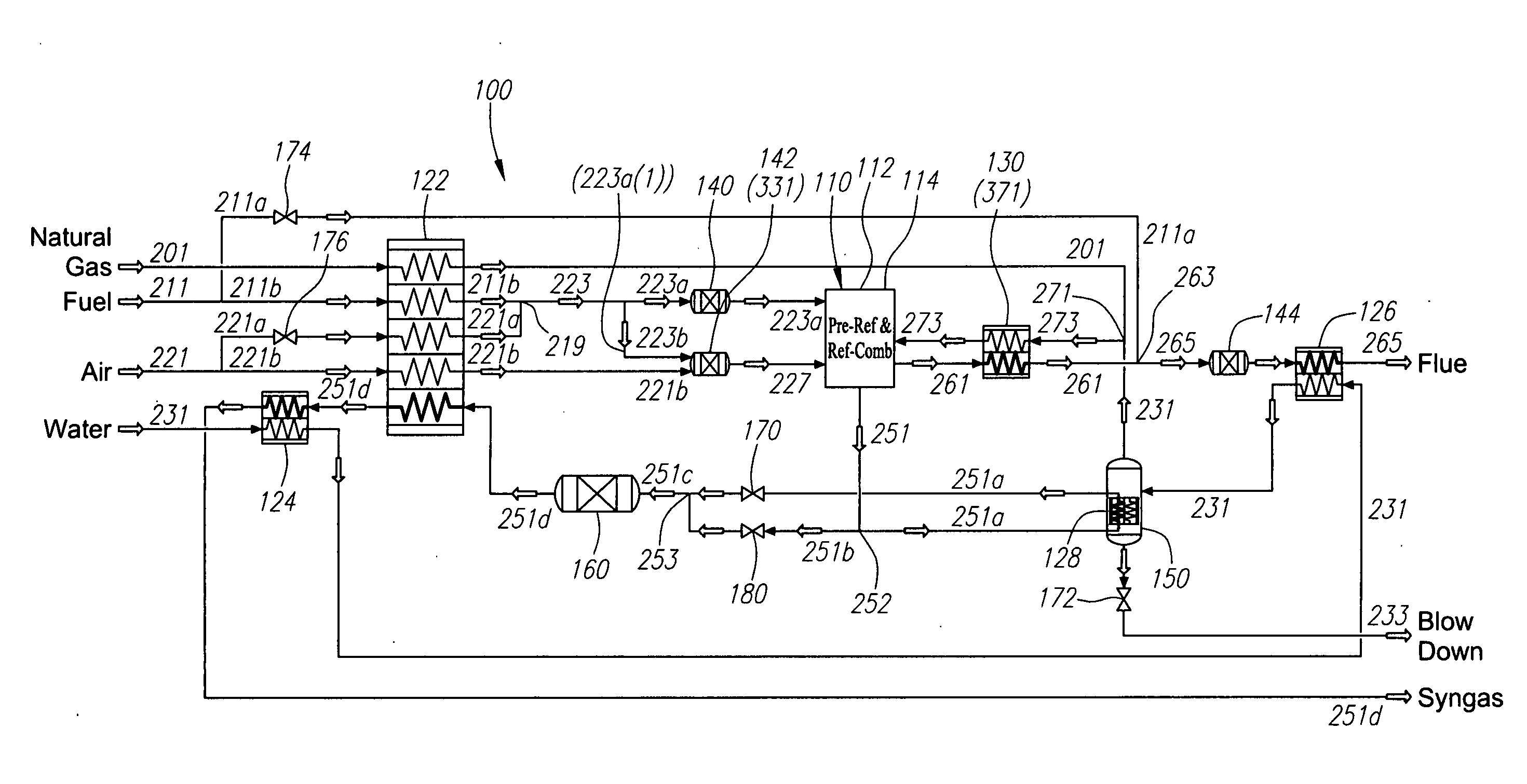
[0175]An alternate reformer embodiment 101 is now described with reference to FIG. 11, with components similar to those in FIG. 10 bearing the same reference numerals. Reformer 101 differs from reformer 100 in that it uses a six-stream heat exchanger 128a instead of the five-stream heat exchanger 128 in FIG. 10.

[0176]Another difference is that fuel line 211 in reformer 101 may split into two lines 211aa and 211b that are both preheated in heat exchanger 128a (as opposed to only line 211b being preheated in heat exchanger 128 of reformer 100). However, fuel line 211aa may eventually join with the flue gas exiting reformer 110 in line 261, at point 263. These variations preferably increase efficiency as more waste heat, from the syngas effluent, may be recovered by the cold feed streams.

[0177]C. Alternate Reformer System

embodiment 102

[0178]An alternate reformer embodiment 102 is now described with reference to FIG. 12. As mentioned previously, reformer 102 does not include combustion chamber 144 prior to heat exchanger 126 as does reformer 100 of FIG. 10. Thus the additional heat that could be imparted to the water in heat exchanger 126 owing to the combustion is not available.

[0179]The reformer embodiment 102 is preferably suited to operate with higher maximum syngas temperatures, e.g., approaching 900° C. At this higher temperature, the additional steam raised with the assistance of combustion chamber 144 in FIG. 10 is not required as reforming at a higher temperature provides higher methane conversion, for a given steam-to-carbon ratio.

[0180]D. Fuel Efficiency

[0181]An aspect of the current invention relating to increased fuel efficiency is now further described.

[0182]Downstream of reformer 110, heat is available from the effluent streams of the reforming process, which are syngas (product) in line 251 and flu...


PUM

PropertyMeasurementUnit
thicknessaaaaaaaaaa
thicknessaaaaaaaaaa
radial depthaaaaaaaaaa

Abstract

A multiple adiabatic bed reforming apparatus and process involving stage-wise combustion and multiple reforming chambers. Co-flow and cross-flow occurs under laminar flow conditions. A reformer suitable for small scale production as well as large scale production. A passive stage-by-stage fuel distribution network suitable for low pressure fuel wherein the resistances in successive fuel distribution lines control the amount of fuel delivered to each combustion stage. Heat is captured from reforming syngas product to preheat gases before entering the reformer. Conditions that would produce unwanted coking or metal dusting are avoided or localized away from the heat exchangers to locations which can be cost effectively protected. A chemical reactor which has a core composed of a stack of metal plates that are diffusion bonded in face-to-face relationship.

Description

CROSS REFERENCE TO RELATED APPLICATIONS[0001]This application is a continuation-in-part of U.S. Ser. No. 10 / 500,176, entitled Chemical Reactor, which claimed priority to PCT Application No. PCT / AU03 / 00022, which application claimed priority to Australian Patent Application No. PR 9817, filed Jan. 4, 2002, the entirety of each of which is incorporated herein by reference.FIELD OF THE INVENTION[0002]The invention generally relates to an improved reformer apparatus and method, including a multiple adiabatic bed reformer that is more efficient and suitable for smaller scale production of gases than are tubular reforming systems. More specifically, the invention relates to improved fuel efficiency, the reduction, avoidance or localizing of metal dusting conditions, distribution of fuel to the system and improved fluid flow configurations during reforming and heat exchange.[0003]This invention in broad terms also relates to an apparatus for use in, and a method of, effecting a chemical re...

Claims


Application Information

Patent Timeline
Patent Type & Authority Applications(United States)
IPC IPC(8): B01J19/00B01J8/02B01J19/24C01B3/38C01B3/48H01M8/04H01M8/06H01M8/10
CPCB01J19/249H01M8/0668B01J2219/2458B01J2219/2465B01J2219/2475B01J2219/2477B01J2219/2497C01B3/38C01B3/48C01B2203/0233C01B2203/0288C01B2203/044C01B2203/047C01B2203/0495C01B2203/066C01B2203/0811C01B2203/0844C01B2203/0866C01B2203/0883C01B2203/1241C01B2203/143C01B2203/146C01B2203/147C01B2203/82H01M8/04022H01M8/0612B01J2219/2453Y02E60/50Y02P20/129Y02P70/50
Inventor JOHNSTON, ANTHONY M.
Owner MEGGIT (UK) LTD
Why Eureka
Try Eureka