

Vehicular diagnostic system
- Summary
- Abstract
- Description
- Claims
- Application Information
AI Technical Summary
Benefits of technology
Problems solved by technology
Method used
Image

Examples
Embodiment Construction
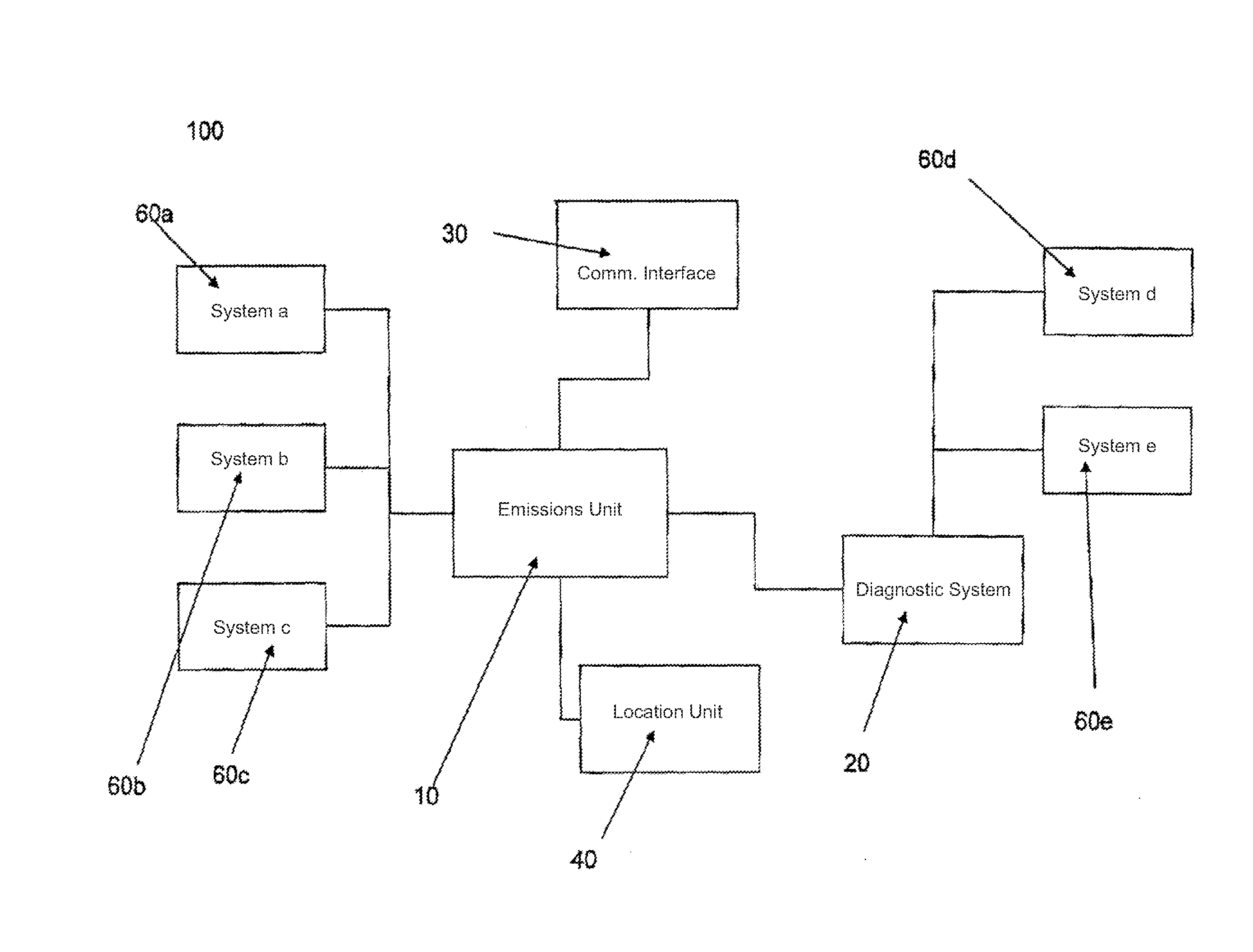
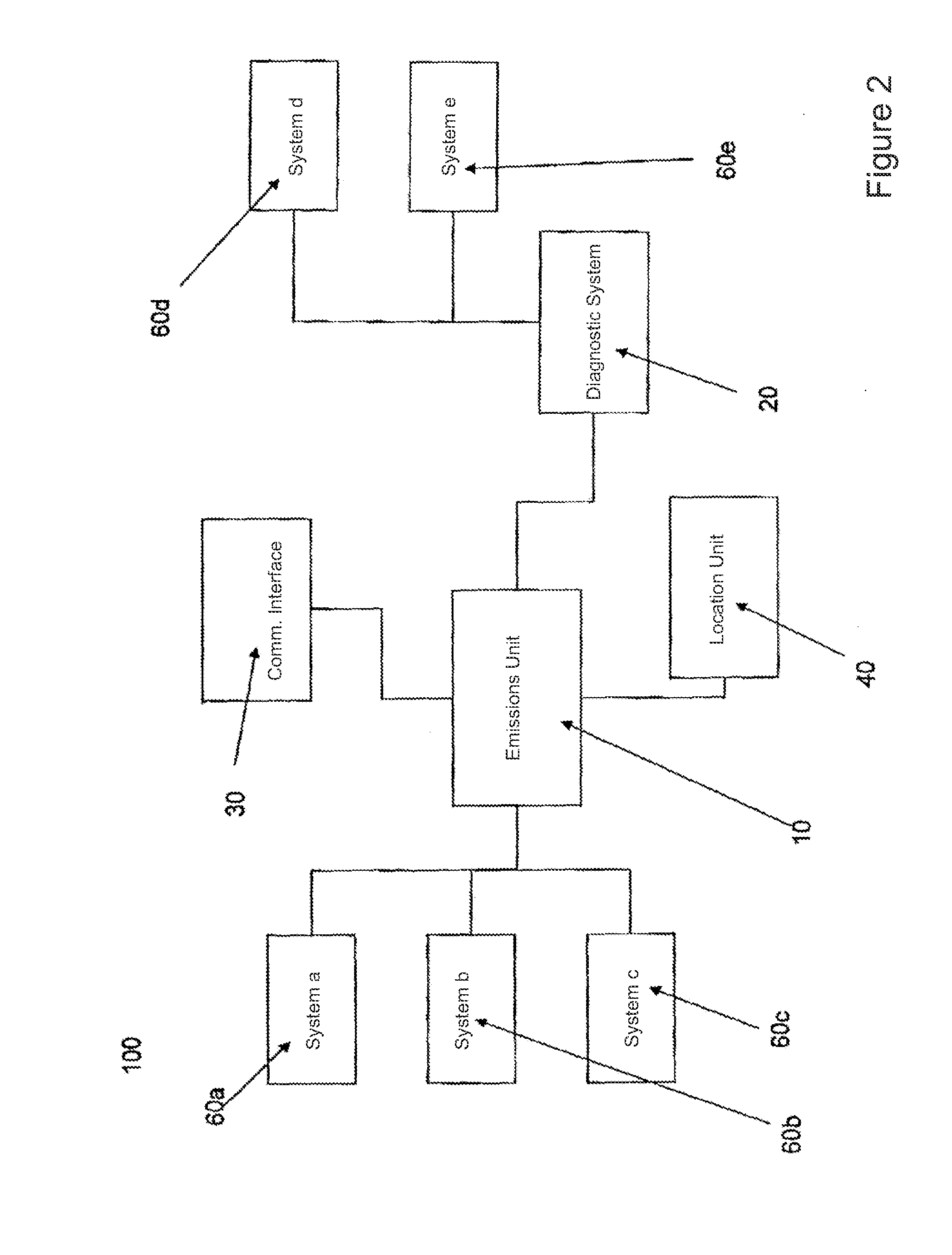
[0030]FIG. 2 shows a schematic depiction of a system 100 according to the present invention under calibration. The system comprises emissions unit 10, vehicle diagnostic system 20, communications interface 30, vehicle location unit 40 and a plurality of vehicle systems and subsystems 60a, 60b, . . . . The emissions unit 10 is connected to the vehicle diagnostic system, which may be for example, the 013D or 0130-11 system. The emissions unit 10 is also connected directly to a plurality of vehicle systems and sub-systems, for example to monitor the engine temperature. This enables additional data to be measured which cannot be received directly from the vehicle diagnostic system or to provide a check against the data being provided by the vehicle diagnostic system. The emissions unit Is also connected to the communications interface 30 and the vehicle location unit 40 (see below).
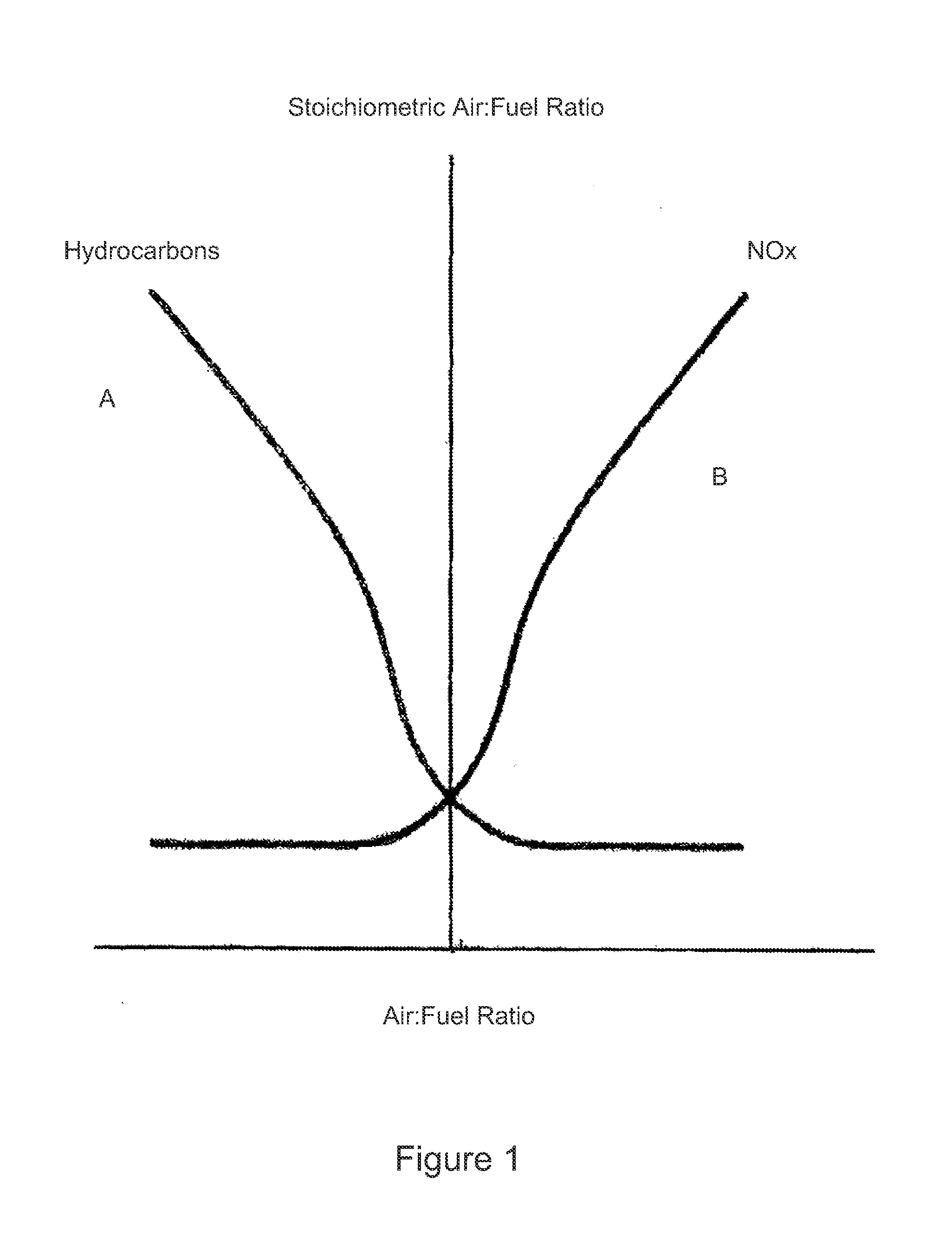
[0031]When under calibration, the vehicle emissions are measured using conventional methods across a wide ...
PUM
 Abstract
Description
Claims
Application Information