Heat recovery method for wellpad sagd steam generation

a heat recovery and wellpad technology, applied in the direction of insulation, ignition automatic control, borehole/well accessories, etc., can solve the problems of large cost of steam generation, large cost of oil production, and decline of natural gas production in canada, so as to save energy in heating feedwater and reduce heat loss , the effect of saving energy

Inactive Publication Date: 2013-03-21
CONOCOPHILLIPS CO
View PDF28 Cites 17 Cited by
  • Summary
  • Abstract
  • Description
  • Claims
  • Application Information

AI Technical Summary

Benefits of technology

[0024]In another embodiment, the feedwater is further preheated at the CPF by the separated produced emulsion before heated by the wellpad heat exchanger at the wellpad, such that even more energy can be saved in heating the feedwater.
[0025]In another embodiment, the invention is a system and method for more cost effective SAGD hydrocarbon recovery, comprising a heavy oil or bitumen reservoir,

Problems solved by technology

The latter were established to be inefficient, resulting in the first test of twin (horizontal) well SAGD in the Athabasca Oil Sands, which proved the feasibility of the concept, briefly achieving positive cash flow in 1992 at a production rate of about 2000 bbl/day from 3 well pairs.
The process is relatively insensitive to shale streaks and other vertical barriers to steam and fluid flow because, as the rock is heated, differential thermal expansion causes fractures in it, allowing steam and fluids to flow through.
As in all thermal recovery processes, the cost of steam generation is a major part of the cost of oil production.
The fact that natural gas production in Canada has peaked and is now declining is also a problem.
In addition to the operati

Method used


Image

  • Heat recovery method for wellpad sagd steam generation
  • Heat recovery method for wellpad sagd steam generation
  • Heat recovery method for wellpad sagd steam generation

Examples


example 1

Heating Feedwater by Produced Emulsion at Wellpad

[0039]An AspenPlus® process model (a process modeling tool supplied by Aspen Technology, Inc.) was used to quantify the benefits of wellpad versus CPF heat recovery. Specifically, the model was used to determine the feedwater preheat temperatures that can be attained for DSG-based SAGD operations.

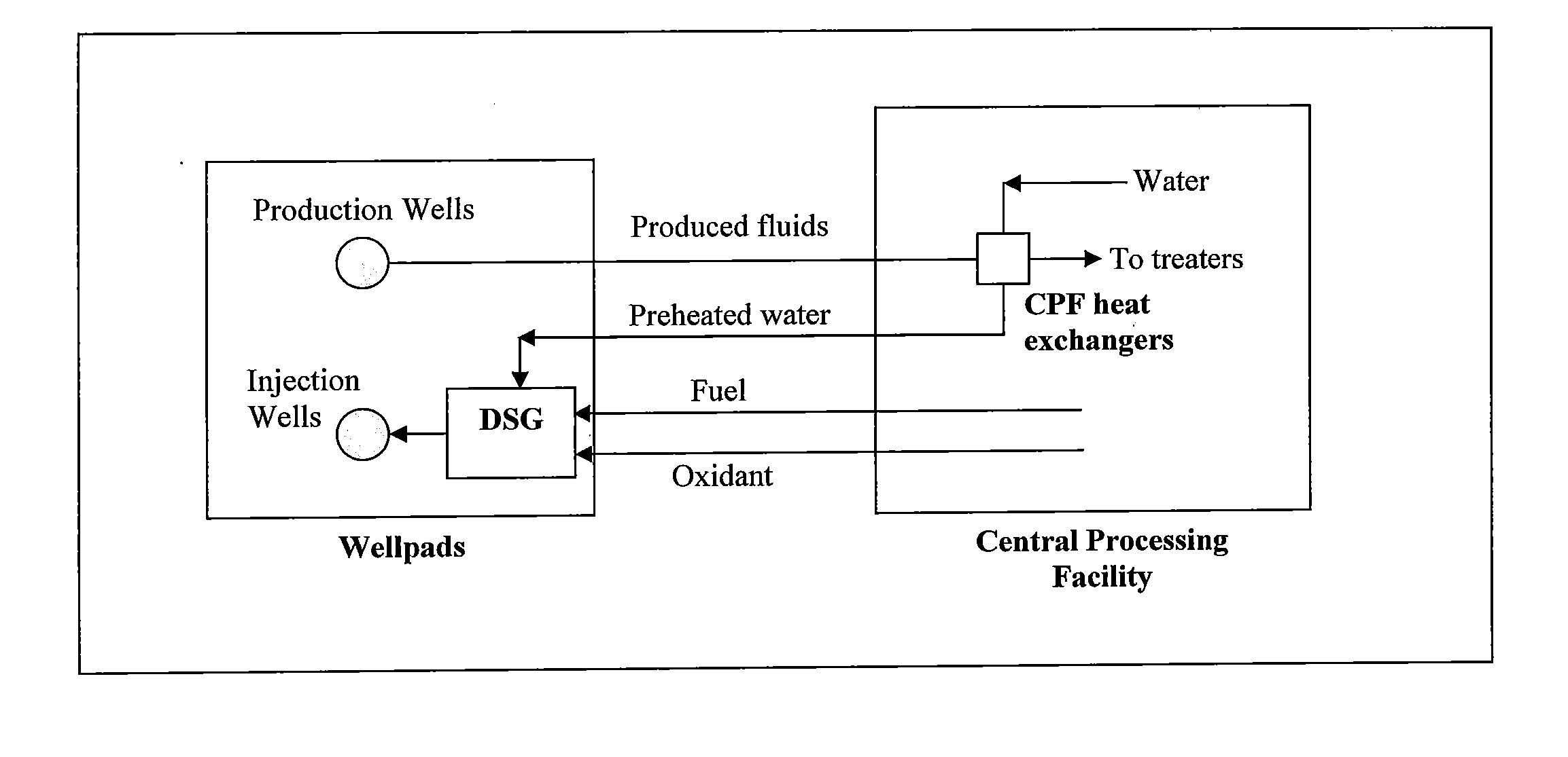
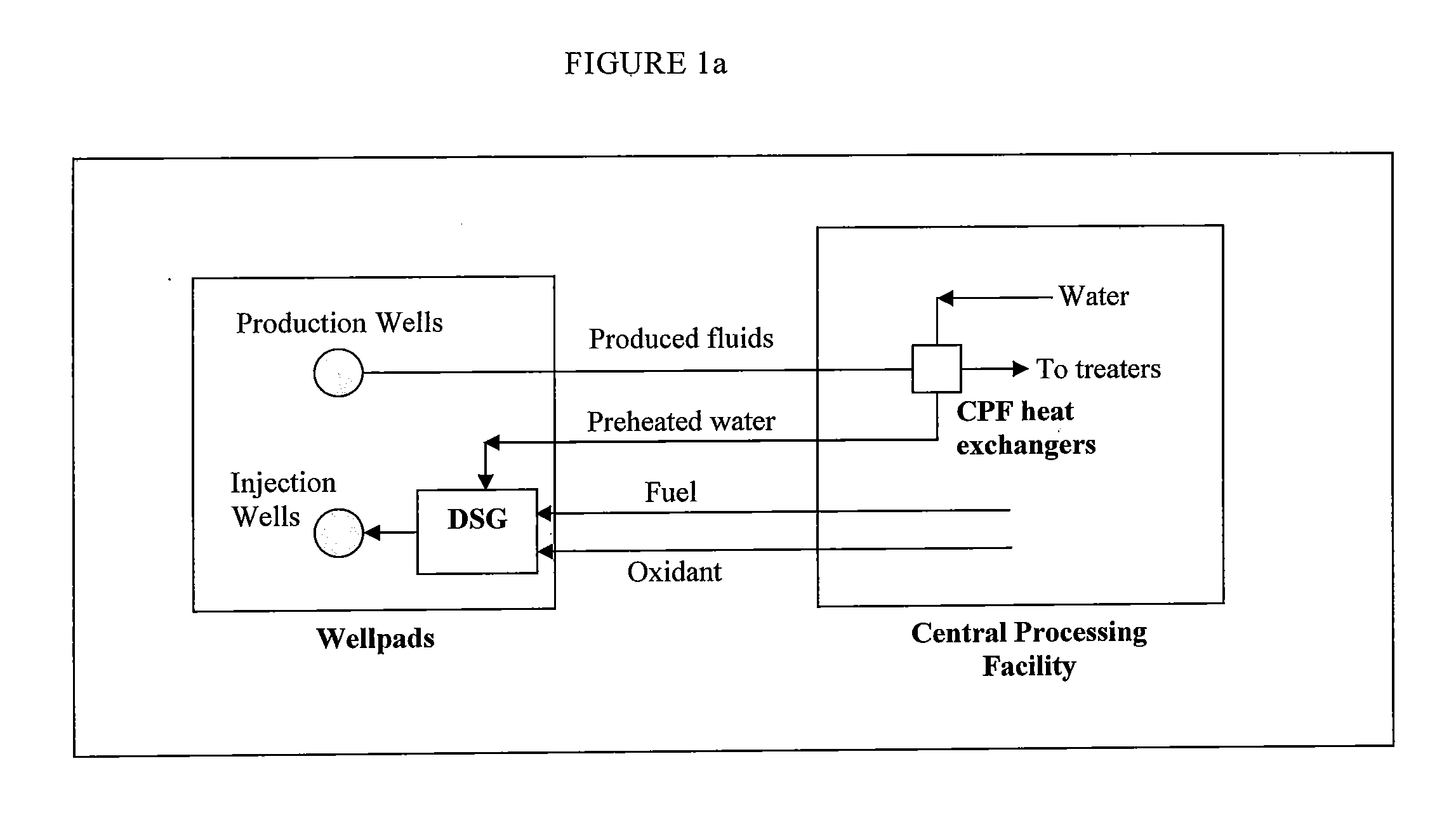
[0040]FIG. 2a shows the CPF heat recovery case where produced fluids at the wellpads are conveyed to the CPF in two separate lines, one containing bitumen / water emulsion, and one containing produced gases. As shown in the figure, this will enable a DSG water preheat temperature of 150° C. at the CPF, which drops to 140° C. at the wellpads assuming a 10° C. temperature drop in the water lines due to ambient heat losses.

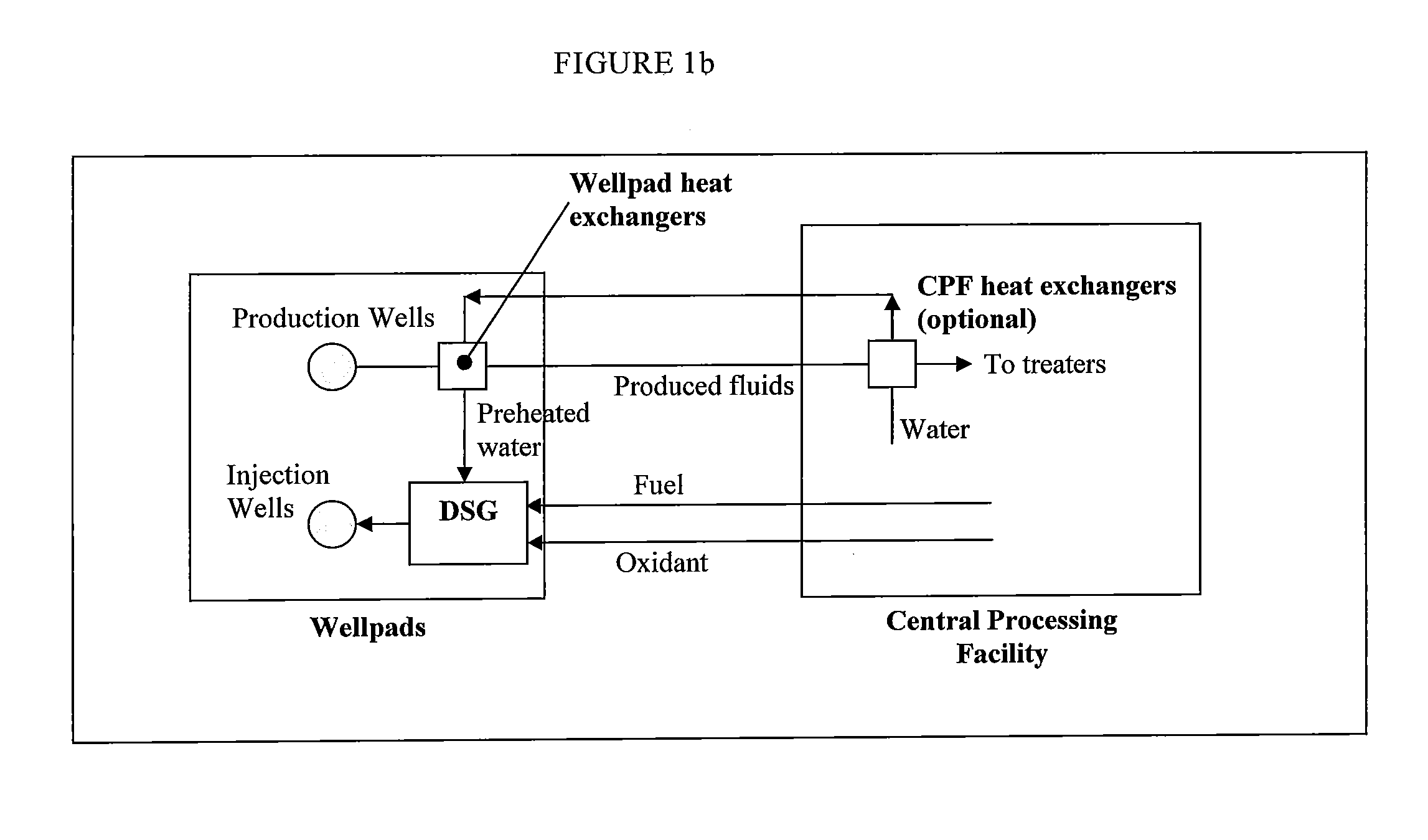
[0041]The wellpad heat recovery case shown in FIG. 2b was based on heat exchange with the produced water / bitumen emulsion at the wellpads and heat exchange with produced gases at the CPF. This was considered a preferred configur...

example 2

Heating Feedwater by Produced Fluids at Wellpad

[0045]The configuration of this example is similar to Example 1 as shown in FIG. 2b, except that the heat exchange takes place between the feedwater and the produced fluids before the produced fluids enter the pad separators. One benefit of such configuration is that even more heat can be recovered from the produced fluids, because some enthalpies may be lost during the separation in the pad separators.

example 3

Heating Feedwater by Produced Gases at Wellpad

[0046]The configuration of this example is similar to Example 1 as shown in FIG. 2b, except that the heat exchange takes place between the feedwater and the produced gases instead of the produced emulsions.


PUM


Abstract

The invention provides a method of recovering heat from hot produced fluids at SAGD facilities that utilize wellpad steam generation such as Direct Steam Generators (DSG).

Description

CROSS-REFERENCE TO RELATED APPLICATIONS[0001]This application is a non-provisional application which claims the benefit of and priority to U.S. Provisional Application Ser. No. 61 / 449,437 filed Mar. 4, 2012, entitled “Heat Recovery Method for Wellpad SAGD Steam Generation,” which is hereby incorporated by reference in its entirety.FEDERALLY SPONSORED RESEARCH STATEMENT[0002]Not applicable.FIELD OF THE INVENTION[0003]The invention relates to a system for improving heat recovery in steam assisted gravity drainage operation.BACKGROUND OF THE INVENTION[0004]Steam Assisted Gravity Drainage (SAGD) is an enhanced oil recovery technology for producing heavy crude oil and bitumen. The gravity drainage idea was originally conceived by Dr. Roger Butler around 1969, and field tested in 1980 at Cold Lake, Alberta, which featured one of the first horizontal wells in the industry with vertical injectors. The latter were established to be inefficient, resulting in the first test of twin (horizontal...

Claims


Application Information

Patent Timeline
IPC IPC(8): E21B43/24F22D1/16
CPCE21B43/40F22D1/16E21B43/2406Y10T137/6416
Inventor MACADAM, SCOTTSEABA, JAMES P.LAMONT, DAVID C.
Owner CONOCOPHILLIPS CO
Why Eureka
Try Eureka