Dual elliptical reflector with a co-located foci for curing optical fibers

a technology of optical fiber and co-located foci, which is applied in the direction of furnaces, drying machines with progressive movements, and therapy, etc., can solve the problems of lowering curing and production rates, irradiating the optical fiber surface, and causing the curing uniformity to rise, so as to achieve the effect of reducing the curing and production rate, and ensuring the long-term durability of performan

Active Publication Date: 2013-03-21
PHOSEON TECHNOLOGY INC
View PDF7 Cites 51 Cited by
  • Summary
  • Abstract
  • Description
  • Claims
  • Application Information

AI Technical Summary

Benefits of technology

[0002]Optical fibers are used ubiquitously in lighting and imaging applications, as well as in the telecommunication industry, where they provide higher data transmission rates over longer distances as compared to electric wiring. In addition, optical fibers are more flexible, lighter, and can be drawn into thinner diameters than metal wiring, allowing for higher-capacity bundling of fibers into cables. Surface coatings, applied via an ultra-violet (UV) curing process, are employed to protect optical fibers from physical damage and moisture intrusion, and to maintain their long-term durability in performance.
[0003]Carter et al. (U.S. Pat. No. 6,626,561) addresses UV curing uniformity issues for optical fibers having surfaces that are located outside a focal point of a UV curing device employing an elliptical reflector to direct UV light from a single UV light source positioned at a second focal point of the elliptical reflector, to the surface of the optical fiber. Curing uniformity issues can arise due to imprecise alignment of the optical fiber relative to the light source, or an irregular-shaped optical fiber. To address these issues, Carter uses a UV lamp structure employing an elliptical reflector to irradiate optical fiber surfaces positioned in the vicinity of a second elliptical reflector focal point with UV light from a single light source positioned in the vicinity of a first elliptical reflector focal point, wherein both the optical fiber and bulb are displaced slightly from the focal points. In this manner, the UV light rays reaching the surface of the optical fiber are dispersed, and the irradiation and curing of the optical coating can potentially be more uniform.
[0004]The inventor herein has recognized a potential issue with the above approach. Namely, by displacing the UV light source and the optical fiber away from the focal points of the elliptical reflector, the intensity of UV light irradiating the optical fiber surfaces is dispersed and reduced, thereby lowering the curing and production rates, and imparting higher manufacturing costs.
[0005]One approach that addresses the aforementioned issues includes a UV curing device, comprising dual elliptical reflectors having a co-located focus, and arranged on opposing sides of a workpiece, and two UV light sources, wherein each light source is located at a second focus of each elliptical reflector. In this manner, it is possible to irradiate optical fibers or other workpieces with UV light both uniformly and with high intensity, providing rapid and uniform cure of optical fiber coatings.

Problems solved by technology

Curing uniformity issues can arise due to imprecise alignment of the optical fiber relative to the light source, or an irregular-shaped optical fiber.
Namely, by displacing the UV light source and the optical fiber away from the focal points of the elliptical reflector, the intensity of UV light irradiating the optical fiber surfaces is dispersed and reduced, thereby lowering the curing and production rates, and imparting higher manufacturing costs.

Method used


Image

  • Dual elliptical reflector with a co-located foci for curing optical fibers
  • Dual elliptical reflector with a co-located foci for curing optical fibers
  • Dual elliptical reflector with a co-located foci for curing optical fibers

Examples


Embodiment Construction

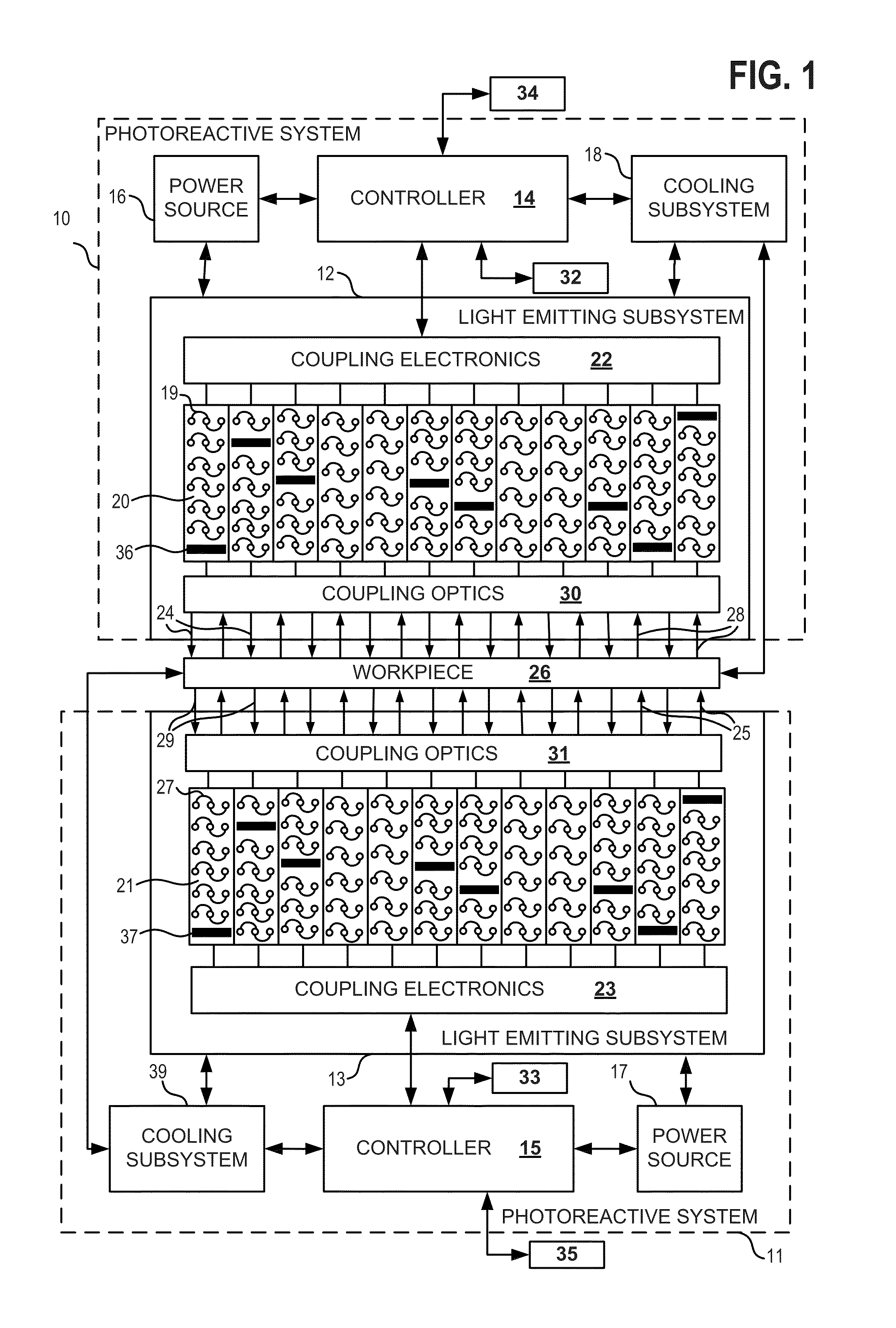
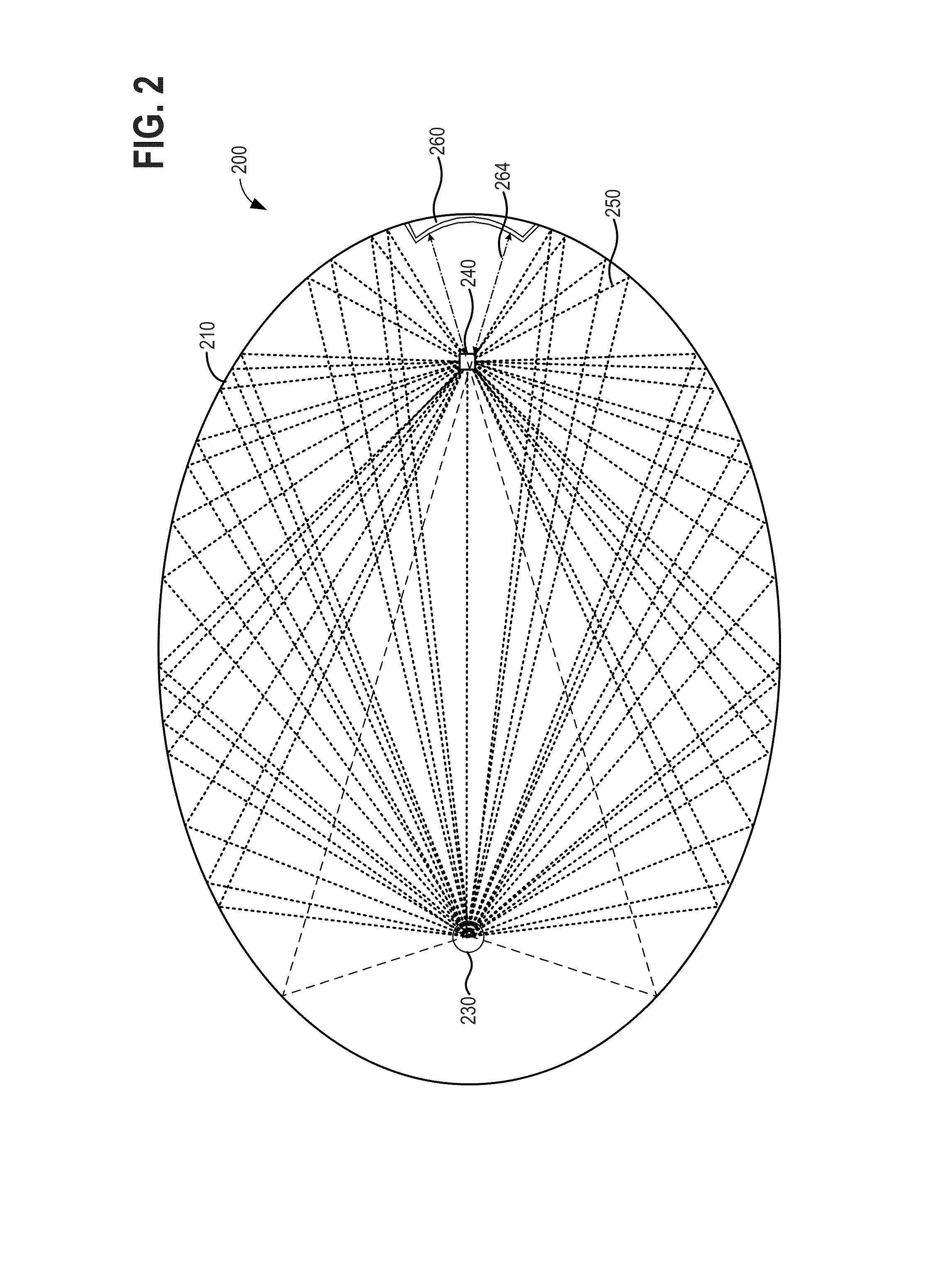
[0014]The present description is for a UV curing device, method and system for use in manufacturing coated optical fibers, ribbons, cables, and other workpieces. Optical fiber coatings may be UV-cured via a UV curing device employing dual elliptical reflectors arranged to have a co-located focus, wherein the workpiece (e.g., the optical fiber) is positioned at the co-located focus, and two UV light sources are located at the second focus of each elliptical reflector. FIG. 1 illustrates an example of dual UV curing devices (e.g., photoreactive systems) including a UV curing device, coupling optics and coupling electronics. FIG. 2 shows a single elliptical reflector coupling optics configuration of a conventional UV curing device for UV curing optical fibers. FIG. 3 illustrates an example of two elliptical surfaces arranged to have a co-located focus. FIG. 4 illustrates a dual elliptical reflector coupling optics configuration of a UV curing device, wherein the dual elliptical reflect...


PUM

PropertyMeasurementUnit
linear speedaaaaaaaaaa
axial lengthaaaaaaaaaa
heataaaaaaaaaa

Abstract

A device for UV curing a coating or printed ink on an workpiece such as an optical fiber comprises dual elliptical reflectors arranged to have a co-located focus. The workpiece is centered at the co-located focus such that the dual elliptical reflectors are disposed on opposing sides of the workpiece. Two separate light sources are positioned at a second focus of each elliptical reflector, wherein light irradiated from the light sources is substantially concentrated onto the surface of the workpiece at the co-located focus.

Description

RELATED APPLICATIONS[0001]The present application claims priority to U.S. Patent Application No. 61 / 535,318, filed on Sep. 15, 2011, the entire contents of which are hereby incorporated by reference.BACKGROUND AND SUMMARY[0002]Optical fibers are used ubiquitously in lighting and imaging applications, as well as in the telecommunication industry, where they provide higher data transmission rates over longer distances as compared to electric wiring. In addition, optical fibers are more flexible, lighter, and can be drawn into thinner diameters than metal wiring, allowing for higher-capacity bundling of fibers into cables. Surface coatings, applied via an ultra-violet (UV) curing process, are employed to protect optical fibers from physical damage and moisture intrusion, and to maintain their long-term durability in performance.[0003]Carter et al. (U.S. Pat. No. 6,626,561) addresses UV curing uniformity issues for optical fibers having surfaces that are located outside a focal point of...

Claims


Application Information

Patent Timeline
Patent Type & Authority Applications(United States)
IPC IPC(8): G21K5/00
CPCC03C25/12G21K1/067F26B13/00G21K2201/064G21K2201/065G21K5/00F26B3/28B05D2256/00B05D3/067
Inventor CHILDERS, DOUG
Owner PHOSEON TECHNOLOGY INC
Why Eureka
Try Eureka