Brushless motor driving apparatus and brushless motor driving method

Active Publication Date: 2013-03-21
HITACHI ASTEMO LTD +1
View PDF11 Cites 12 Cited by
  • Summary
  • Abstract
  • Description
  • Claims
  • Application Information

AI Technical Summary

Benefits of technology

The present invention is a brushless motor driving apparatus that regulates the voltage to switch between phases of a brushless motor. It uses the voltage change in a non-energized phase and a voltage threshold to sequentially switch the phases. Additionally, the apparatus regulates the upper threshold for the energy amount based on the voltage change and the timing of switching between phases. The technical effects of this invention include better control over the motor's rotation and more efficient energy usage.

Problems solved by technology

However, in a brushless motor drive technique as described above, there is a possibility that the duty ratio for a PWM (Pulse Width Modulation) control increases, thereby causing synchronism loss in the brushless motor.
Consequently, energization modes for the brushless motor fail to switch with appropriate timing so that synchronism loss is caused in the brushless motor.

Method used


Image

  • Brushless motor driving apparatus and brushless motor driving method
  • Brushless motor driving apparatus and brushless motor driving method
  • Brushless motor driving apparatus and brushless motor driving method

Examples


Embodiment Construction

[0024]Hereinafter an embodiment of the present invention will explained in detail with reference to the attached drawings.

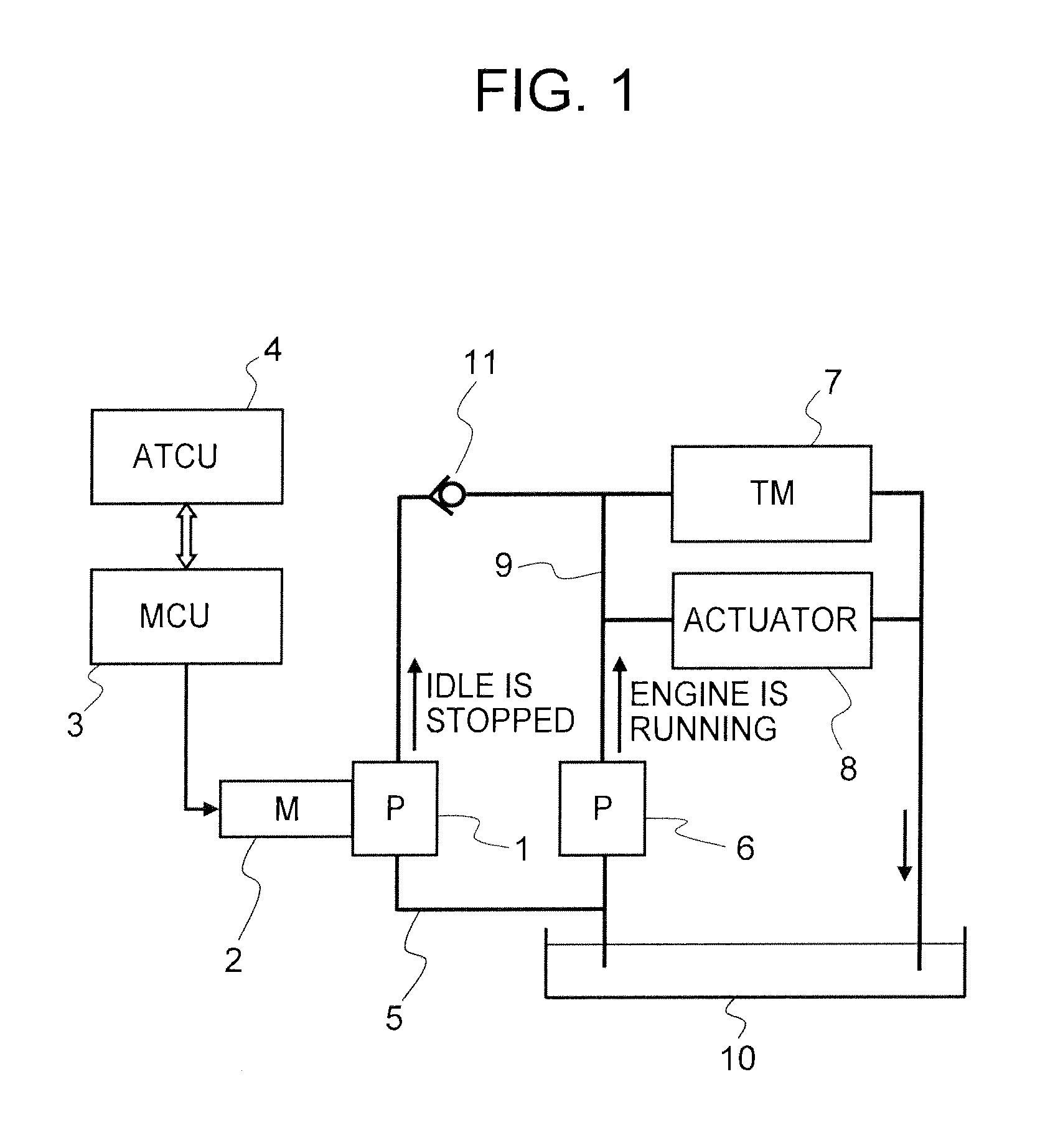
[0025]FIG. 1 is a schematic view of a hydraulic pump system for a vehicle AT, as an example of the systems in which a brushless motor driving apparatus is applied.

[0026]For use as an oil pump for supplying oil to a transmission 7 and an actuator 8, the hydraulic pump system for the vehicle AT includes: a mechanical oil pump 6 which is driven by output from an engine (not illustrated); and a motor-driven oil pump 1 which is driven by a motor.

[0027]A control system for the engine includes an idle stop control mechanism that stops the engine when conditions for automatic stop are satisfied and restarts the engine when conditions for automatic start are satisfied. While the engine is stopped by stopping idle, the operation of mechanical oil pump 6 is also stopped. Therefore, during idle stop, motor-driven oil pump 1 is actuated to supply oil to transmission 7 and act...


PUM


Abstract

A brushless motor driving apparatus that rotates and drives a brushless motor, which has a plurality of coils, by switching energization modes corresponding to phases of the brushless motor, sequentially switches the energization modes based on a non-energized phase voltage and a voltage threshold. Also, the brushless motor driving apparatus regulates an upper threshold for energization amount based on the voltage threshold and a change in the non-energized phase voltage at timing of switching the energization mode.

Description

BACKGROUND OF THE INVENTION[0001]1. Field of the Invention[0002]The present invention relates to a brushless motor driving apparatus and a brushless motor driving method.[0003]2. Description of Related Art[0004]As a technique for driving a brushless motor at low speed without a sensor, one in which energization mode is switched according to induced voltage (magnetic saturation voltage) in a non-energized phase has been proposed, as described in JP 2009-189176 A.[0005]However, in a brushless motor drive technique as described above, there is a possibility that the duty ratio for a PWM (Pulse Width Modulation) control increases, thereby causing synchronism loss in the brushless motor. That is, in a state in which the brushless motor is feedback-controlled in an extremely low speed area, when a brushless motor does not reach a target rotational speed due to, for example, a high load, control is performed to increase the duty ratio. In this case, electric current also increases with the...

Claims


Application Information

Patent Timeline
IPC IPC(8): H02P6/18H02P6/06H02P6/08H02P6/17H02P6/182
CPCH02P6/165H02P6/181H02P6/182H02P6/17
Inventor HANO, MASAKIOKAMOTO, NAOKI
Owner HITACHI ASTEMO LTD
Why Eureka
Try Eureka