
Optical communication system, optical receiver, optical transponder, wavelength multiplexing optical communication system, wavelength multiplexing receiving device, and wavelength multiplexing optical transponder

a communication system and optical fiber technology, applied in the field of optical communication systems, can solve the problems of limited transmission distance, limited transmission distance, and inability to bring into reality the trunkline optical communication system having a transmission distance about 500 km, and achieve the effect of low cost, reduced optical fiber online, and simple configuration of the communication system according to the present invention

Inactive Publication Date: 2013-03-21
HITACHI LTD
View PDF28 Cites 26 Cited by
  • Summary
  • Abstract
  • Description
  • Claims
  • Application Information

AI Technical Summary

Benefits of technology

The present invention is about an optical OFDM communication system that can achieve high optical power with almost no PAPR (Peak-to-Average Power / Peak-to-Peak) in the transmission path, reducing sensitivity degradation caused by nonlinearity of the optical fiber. This system can be used for long-distance transmission and is cost-effective compared to communication systems using coherent receiving format. Additionally, a direct detection receiving format is used in the invention, making the communication system simpler and more affordable.

Problems solved by technology

However, these measures in which it is intended to drastically increase the communication capacity by increasing the modulation speed have the following problem.
There is a problem in that, if the modulation speed is increased, a transmission distance is limited by the chromatic dispersion of an optical fiber.
In addition, there is another problem in that, if the modulation speed is increased, a transmission distance is limited by the polarization mode dispersion of the optical fiber.
In addition, if the same fiber is used in the next-generation 100 Gbps system, the transmission distance limited by the chromatic dispersion becomes 0.6 km, hence a trunkline optical communication system having a transmission distance about 500 km can not be brought into reality with the use of the same fiber as it is.
This special fiber is expensive, and a sophisticated design is needed to determine the amounts of dispersion compensation fibers respectively installed in the transceivers and the optical transponders, which leads to an advance on the cost of the optical communication system.
As a result, the transmission distance limited by the above-described chromatic dispersion and the polarization mode dispersion becomes much longer than a transmission distance expected in the optical communication system (for example, much longer than 500 km in a domestic trunkline system), hence the above-described dispersion compensation fibers become unnecessary.
Both in an optical communication system and in a wireless communication system, the fact that a PAPR (peak-to-average power ratio) is large causes a problem.
In the case of the wireless communication system, if the linearity of a power amplifier that drives a transmission antenna is inferior, signals are distorted at a peak power, which leads to receiver sensitivity degradation, or interference in adjacent channels owing to the spread of the signal spectra.
In the optical communication system, there is a problem that is caused by a large PAPR and unique to an communication using optical fibers.
In a communication system with the use of single wavelength light, the phase rotation of a signal occurs owing to the peak power of the signal itself (this phenomenon is called a self-phase modulation effect), which brings about a waveform distortion owing to a chromatic dispersion, and leads to the increase in the error rate of this communication system.
In addition, in a wavelength multiplexing optical communication system, the phase rotation of a signal is induced by the peak powers of signals that have adjacent wavelengths (this phenomenon is called a cross-phase modulation effect), which also leads to the increase in the error rate of this communication system.

Method used


Image

  • Optical communication system, optical receiver, optical transponder, wavelength multiplexing optical communication system, wavelength multiplexing receiving device, and wavelength multiplexing optical transponder
  • Optical communication system, optical receiver, optical transponder, wavelength multiplexing optical communication system, wavelength multiplexing receiving device, and wavelength multiplexing optical transponder
  • Optical communication system, optical receiver, optical transponder, wavelength multiplexing optical communication system, wavelength multiplexing receiving device, and wavelength multiplexing optical transponder

Examples


first embodiment

1. First Embodiment

[0174]A first embodiment will be described with reference to FIG. 1 and the like. Although it will be assumed that a modulation format for subcarriers is 4-QAM for convenience of explanation hereinafter, a modulation format that can be used in the present invention is not limited to 4-QAM, and any subcarrier modulation format can be used. In addition the number of subcarriers is assumed to be N (N is 1 or a larger integer).

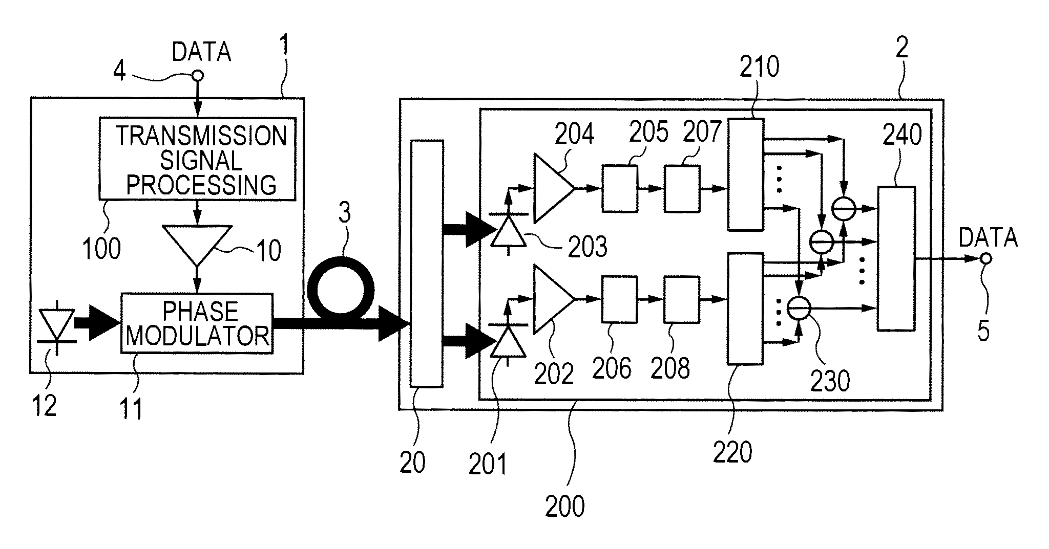
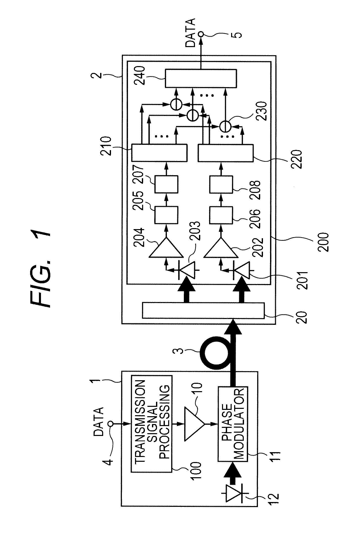
[0175]FIG. 1 shows a block diagram of an optical OFDM communication system.

[0176]The optical OFDM communication system includes, for example, an optical transmitter 1, an optical fiber 3, and an optical receiver 2. The optical transmitter 1 includes, for example, a transmission signal processing unit 100, a drive amplifier 10, an optical phase modulator 11, and a laser source 12. The optical transmitter 1 can includes an input terminal 4. The optical receiver 2 includes a delay interferometer 20, a balanced optical receiving unit 200. The optica...

second embodiment

2. Second Embodiment

[0208]An optical transponder according to a second embodiment will be described with reference to FIG. 15. This optical transponder is a device including an optical transmitter 1 and an optical receiver 2 mounted on a chassis or on a board. Therefore, the optical transponder includes two optical fibers 3-1 and 3-2. The optical fiber 3-1 is used for transmitting optical signals, and the optical fiber 3-2 is used for receiving optical signals. As the optical transmitter 1 and the optical receiver 2 of an optical transponder 700, those used in the above described embodiments can be used accordingly. To put it concretely, although the optical transmitter and the optical receiver shown in FIG. 1 are used in FIG. 15, any one of the optical receivers 2 shown in FIGS. 6, 7, 8 and 10 can be used as the optical receiver.

third embodiment

3. Third Embodiment

[0209]A third embodiment will be described with reference to FIG. 16. FIG. 16 is a block diagram of the entirety of a wavelength multiplexing communication system according to a third embodiment. This system is an optical communication system in which plural digital information signals are converted to wavelength multiplexing signals by a wavelength multiplexing transmitting device 800; these wavelength multiplexing signals are transmitted to a wavelength multiplexing receiving device 900 via an optical fiber 3 which is a transmission path; and the plural original digital signals are restored. The wavelength multiplexing transmitting device receives the plural digital information signals from input terminals 4-i (i=1, 2, . . . , n). The received digital signals are respectively converted to optical signals phase-modulated by optical transmitters 1-i (i=1, 2, . . . , n). The wavelengths of the optical signals output from the optical transmitters 1-i (i=1, 2, . . . ...


PUM


Abstract

To reduce PAPR in an optical OFDM communication system, light is phase-modulated by a base-band OFDM signal which is the output of a transmission signal processing unit 100 provided in an inner section of an optical receiver. When optical communication is implemented with the light as signal light, PAPR of low level of almost 0 dB can be achieved at places in an inner section of an optical fiber wherein the optical power is large. The signal light is propagated along an optical fiber which is a transmission path, the light is passed through a delay interferometer, and converted to electrical signals by two optical receivers. Each of the two electrical signals is converted to a subcarrier by FFT signal processing and an AD converter disposed in an inner section of the optical receivers, then, subcarriers having the same frequency are subtracted and decoded, and data is regenerated.

Description

TECHNICAL FIELD[0001]The present invention relates to optical OFDM communication systems, optical receivers, optical transponders, wavelength multiplexing optical communication systems, wavelength multiplexing receiving devices, and multiplexing optical transponders, and more particularly, relates to an optical communication system and the like that utilize multi-carriers. To put it more concretely, the present invention relates to an optical communication system and the like that reduce a PAPR (peak-to-average power ratio) in an optical OFDM (orthogonal frequency division multiplexing) communication system.BACKGROUND ART[0002]Optical communication systems that have been put into practice so far utilize binary modulation / demodulation techniques with the use of optical intensity. To put it concretely, “0” and “1” of a digital information signal are converted to on-off of the optical intensity of light on a sending side, and fed into an optical fiber, and the light that is propagated ...

Claims


Application Information

Patent Timeline
IPC IPC(8): H04J14/02H04B10/50H04B10/66
CPCH04B10/548H04B10/66
Inventor SASAKI, SHINYA
Owner HITACHI LTD
Learn More