Injection device in molding machine

a molding machine and injection device technology, applied in the field of injection device in the molding machine, can solve the problems of reducing the temperature of the synthetic resin raw material flowing and moving through the through-hole in the moving process, hardly maintaining the uniform melting state, etc., to achieve uniform and well-balanced accelerate the melting of the pellet, and reduce the thermal conductivity

Active Publication Date: 2013-03-21
CENTURY INNOVATION CORP
View PDF2 Cites 9 Cited by
  • Summary
  • Abstract
  • Description
  • Claims
  • Application Information

AI Technical Summary

Benefits of technology

[0039]Next, according to the fifth aspect of the present invention, the melting hole of the melting instrument is formed into a cone-shape. Therefore, the outer periphery of the pellet is easily surrounded by the inner peripheral wall face of the melting hole, irrespective of the shape of the pellet. Therefore substantially uniform and well-balanced melting of the pellet is achieved.
[0040]According to the sixth aspect of the present invention, each inflow-side large opening of the adjacent melting holes is formed into substantially a polygonal shape, and a portion as a boundary between adjacent inflow-side large openings is formed into substantially a linear blade shape. Therefore, the pellet pressed by the inflow-side large opening side plunger of the melting hole in the melting instrument, is crushed finely at a blade-shaped portion on the boundary between inflow-side large openings as described above, thus allowing the pellet to further easily enter from the inflow-side large opening to thereby accelerate the melting of the pellet.
[0041]According to the seventh aspect of the present invention, the air vent section constituted of a plurality of small holes is formed in the area in the peripheral direction near the pellet supply port portion of the cylinder. Therefore, a plurality of pellets can be easily sent into the cylinder. Namely, if the air remains in the cylinder, such a remained air can be discharged from a plurality of small holes, to thereby prevent a situation that the pellet sent into the cylinder is hardly allowed to enter.
[0042]Further, owing to the plurality of small holes of the air vent section, a material area that forms the cylinder can be reduced, thus also reducing the thermal conductivity, and a high temperature state extending to the driving unit can be prevented, and heat dissipation can be set in an excellent state. In addition, the plurality of small holes enables visual observation of inside of the cylinder, and therefore residual quantity of the pellet charged into the cylinder can be confirmed visually.

Problems solved by technology

Therefore, the temperature of the synthetic resin raw material flowing and moving through the through-hole is decreased in the moving process, and a uniform melting state is hardly maintained, thus injecting the synthetic resin raw material including a defect factor such as a heat stress.

Method used


Image

  • Injection device in molding machine
  • Injection device in molding machine
  • Injection device in molding machine

Examples


Embodiment Construction

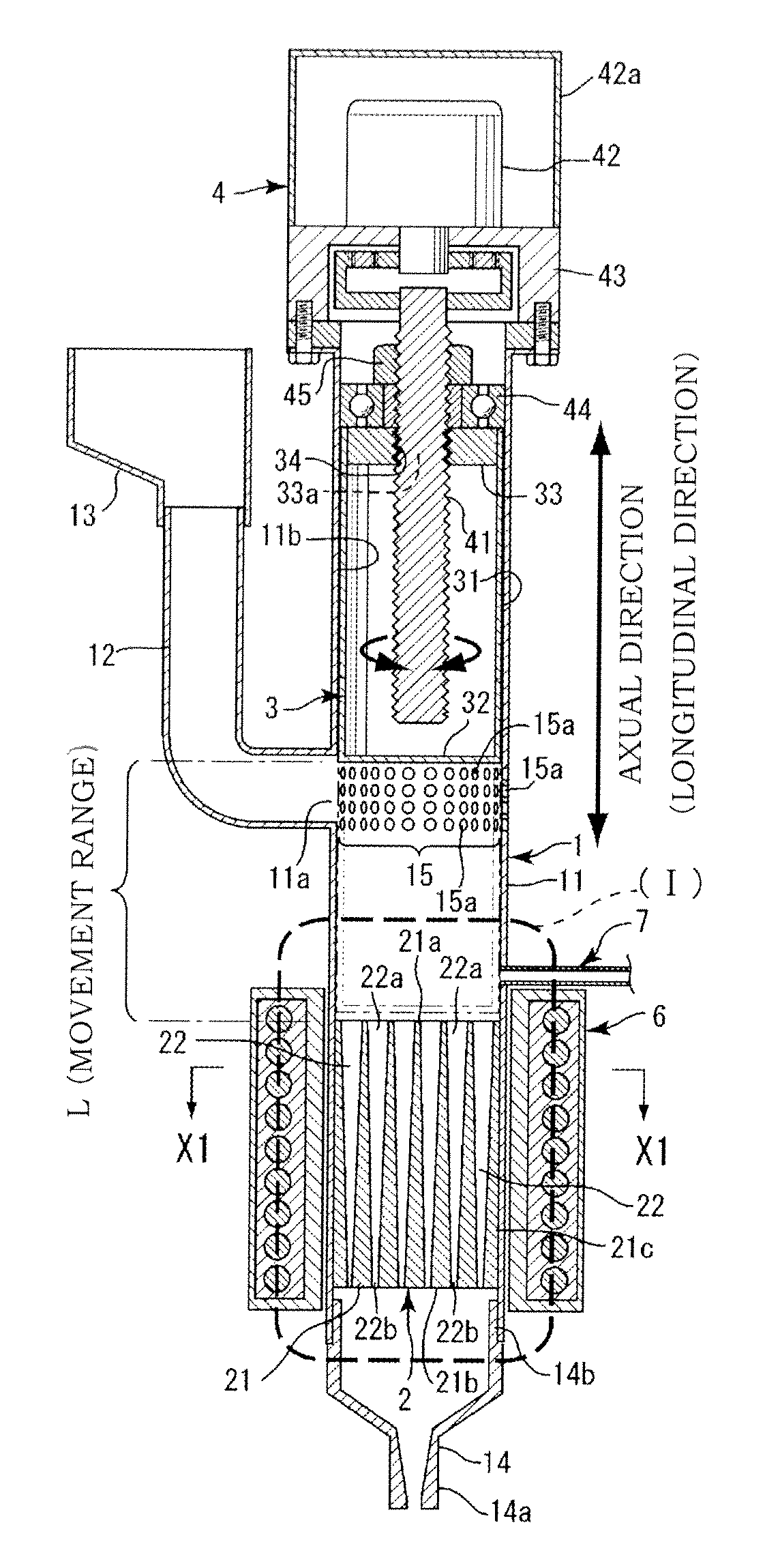
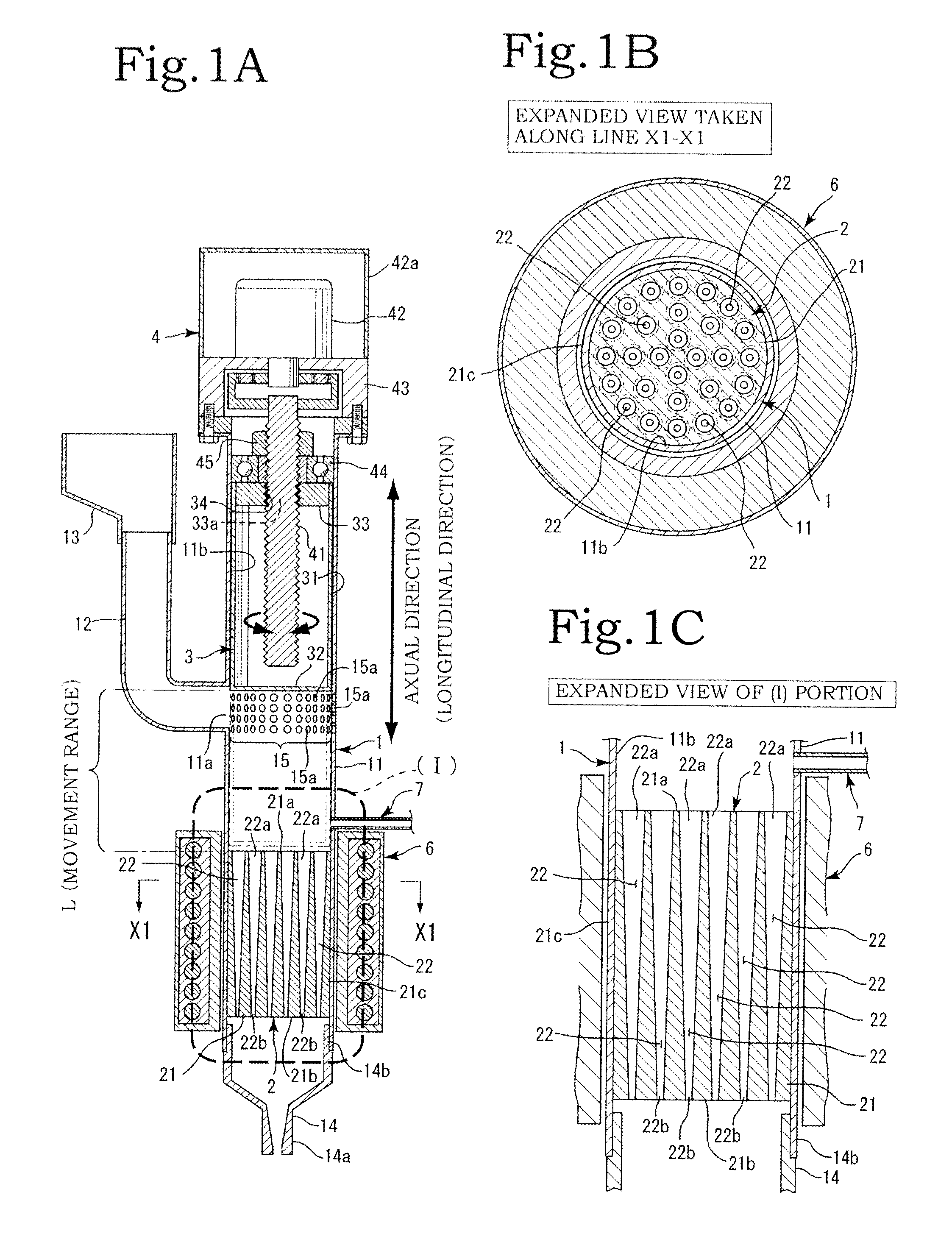
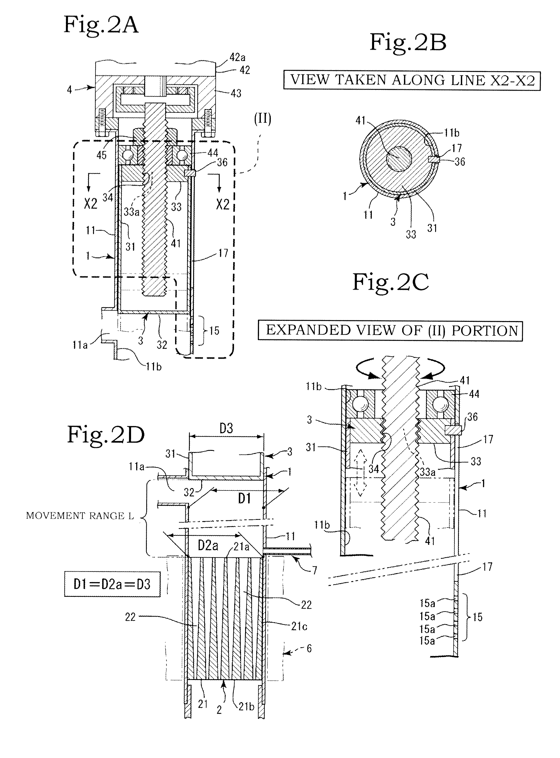
[0052]The present invention will be described hereafter based ore the drawings. As shown in FIG. 1A, the present invention is mainly constituted of a cylinder 1; a melting instrument 2 for melting pellets p; a plunger 3; a driving unit 4 for driving the plunger 3; and a heating unit 6. The melting instrument 2 and the plunger 3 are disposed inside of the cylinder 1.

[0053]A nozzle 14 is mounted on one end side of the cylinder 1 in an axial direction (longitudinal direction), and the driving unit 4 is mounted on the other end side in the axial direction (longitudinal direction), so that the plunger 3 is reciprocally moved though the cylinder 1 in the axial direction (longitudinal direction) by the driving unit 4 (see FIGS. 2A to 2C). The shape of a tip-end face of the plunger 3 is the same shape as the shape of an inflow side face 21a of the melting machine 2.

[0054]The cylinder 1 is made of a material which needs to be speedily heated, and iron or stainless with large content of iron ...


PUM

PropertyMeasurementUnit
thermal conductivityaaaaaaaaaa
diameteraaaaaaaaaa
diameteraaaaaaaaaa

Abstract

A injection device in molding machine is capable of efficiently heating and melting a plurality of charged pellets in a short period of time, and injecting a melting resin with superior quality.
The injection device has a cylinder including a pellet supply port, a plunger, a driving unit, a melting instrument with a plurality of melting holes, which are cone-shaped passages, formed in a cylinder-shaped instrument body to communicate from inflow-side large openings to outflow-side small openings, a nozzle provided on an injection side of the cylinder and a heating unit heating the melting instrument. A diameter of the tip-end of the plunger is set to be the same as a diameter of the outflow side face of the melting machine.

Description

BACKGROUND OF THE INVENTION[0001]1. Field of the Invention[0002]The present invention relates to an injection device in a molding machine capable of efficiently heating and melting a plurality of charged pellets in a short period of time, and injecting a melting resin with superior quality.[0003]2. Description of the Related Art[0004]Generally, there are screw-type and plunger-type injection devices. Japanese Patent Application Laid-Open No. H6-246802 discloses a screw-type injection device typically, which is mainly constituted of a cylinder and a screw. Pellets charged from a hopper provided in the cylinder are transferred to an injection nozzle side by rotation of the screw inside of the cylinder, and are heated and melted in a transfer process. Then, the melted resin is collected to a tip-end of the nozzle, which is then injected, and the melted resin thus obtained is sent to a molding die.[0005]A general pellet is made of resin (plastic), and a thermal conductivity thereof is a...

Claims


Application Information

Patent Timeline
Patent Type & Authority Applications(United States)
IPC IPC(8): B29C45/74
CPCB29C45/53B29C45/74
Inventor KAWASAKI, HIROAKI
Owner CENTURY INNOVATION CORP
Why Eureka
Try Eureka