
Planetary gear unit

a technology of planetary gear and flange, which is applied in the direction of gearing details, belts/chains/gearrings, gearing elements, etc., can solve the problems of large number of bolts required, and large number of threaded bores for receiving bolts, so as to reduce the size of the planetary gear unit, reduce the noise of gears, and ensure the positional accuracy of the case hole and the flange hole. , the effect o

Active Publication Date: 2013-03-21
AISIN AW CO LTD +1
View PDF4 Cites 5 Cited by
  • Summary
  • Abstract
  • Description
  • Claims
  • Application Information

AI Technical Summary

Benefits of technology

The patent aims to offer a solution for reducing gear noise and size of a planetary gear unit. The conventional method of using bolts to fasten the gear unit to the case requires a large number of bolts and results in increased space requirement, which makes the gear mechanism larger in size. The present invention proposes a solution that can achieve both reduction in gear noise and size reduction of the planetary gear unit.

Problems solved by technology

With the ring gear flange fastened to the case using the bolts, however, torque is received by a seat surface friction force generated by the axial forces of the bolts, and a large number of bolts are required to support large torque.
Consequently, a space for a large number of threaded bores for receiving the bolts is required.

Method used


Image

  • Planetary gear unit
  • Planetary gear unit
  • Planetary gear unit

Examples


Embodiment Construction

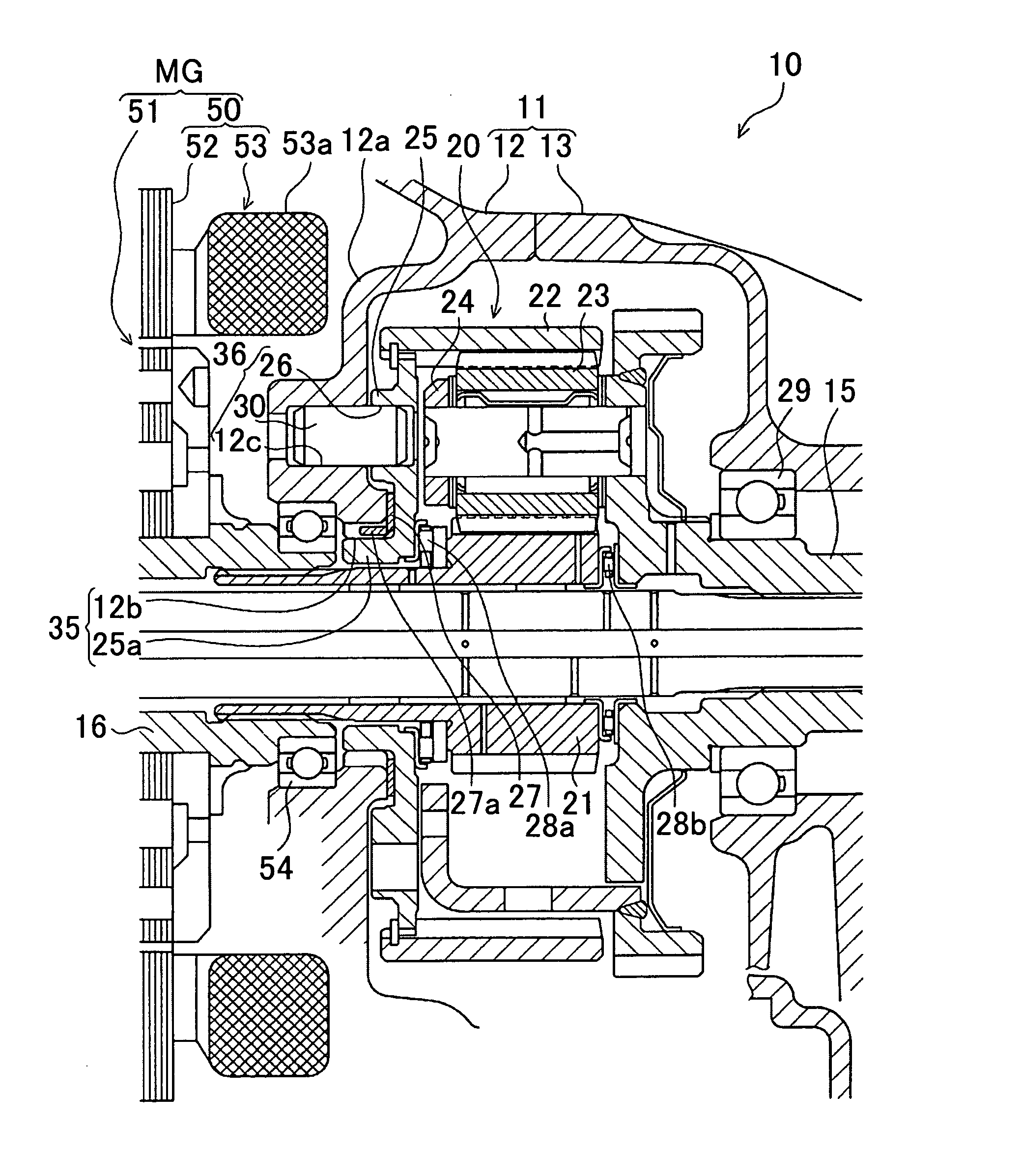
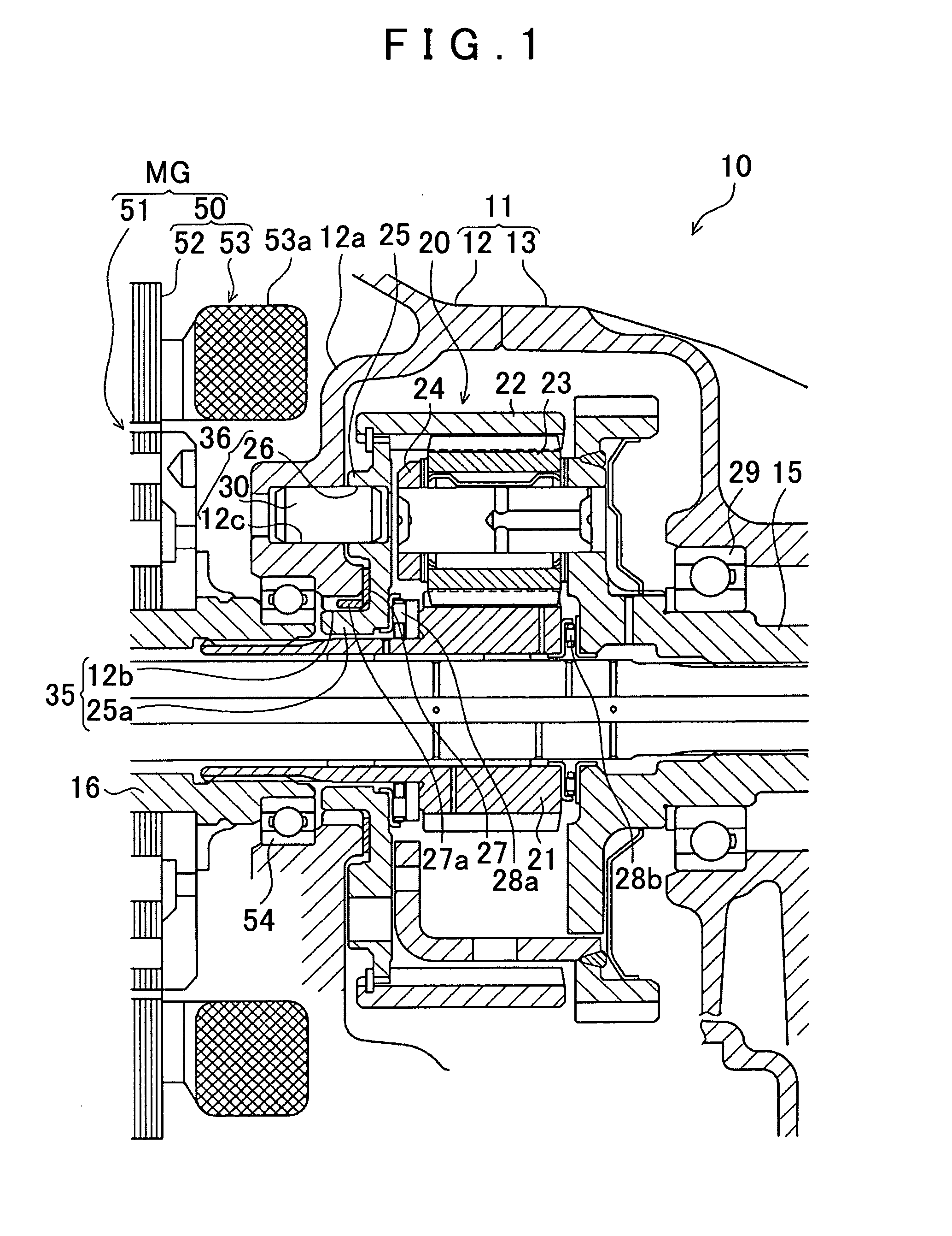
[0045]A vehicle drive device having a planetary gear unit according to a preferred embodiment of the present invention will be described in detail below with reference to the drawings. The embodiment is a longitudinally-mounted drive device to be mounted on a front-engine rear-drive (FR) hybrid vehicle. The drive device according to the embodiment will be described with reference to FIG. 1. FIG. 1 is a sectional view showing a schematic configuration of the drive device according to the embodiment, and showing the area around a speed reduction mechanism (planetary gear unit).

[0046]As shown in FIG. 1, a drive device 10 according to the embodiment includes a motor generator MG, a speed reduction mechanism 20 (planetary gear unit) connected to the motor generator MG, and an output shaft 15 connected to the speed reduction mechanism 20. These components are housed inside a transmission case 11 formed from a main housing 12 and an extension housing 13. The main housing 12 and the extensi...


PUM


Abstract

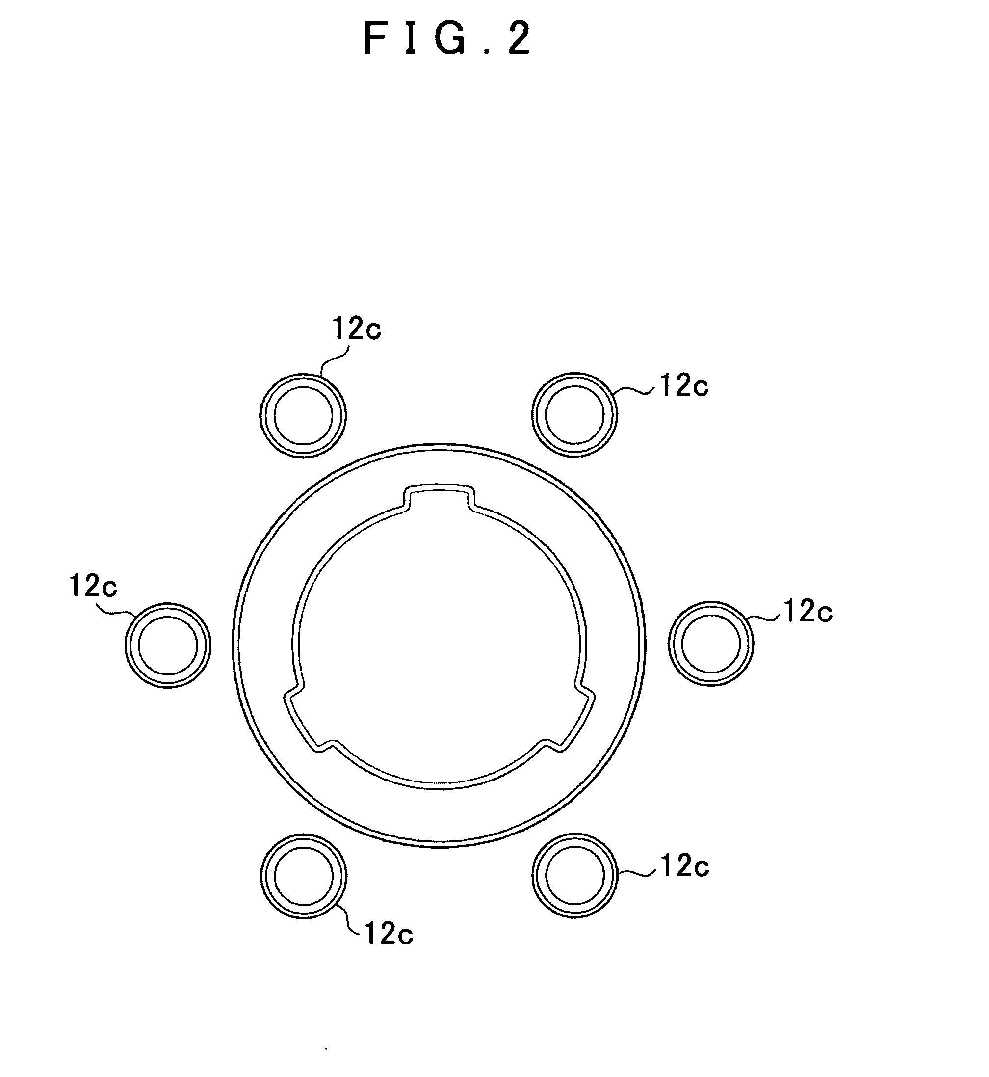
A planetary gear unit inside a case includes coaxial sun and ring gears, a planetary pinion gear that meshes with the sun and ring gears, and a carrier that holds the planetary pinion gear, the ring gear being fixed with respect to the case, and a flange disposed inward of the ring gear. The ring gear is fixed to a case wall, via the flange, the wall extending radially inward, and the flange being prevented from rotating with respect to the wall by a rotation prevention mechanism. The rotation prevention mechanism includes a plurality of case holes on the same circle in the wall, flange holes in the flange at positions corresponding to the case holes, and rotation prevention members fitted into the case and flange holes to prevent rotation of the flange with respect to the wall with the flange relatively movable axially with respect to the wall.

Description

INCORPORATION BY REFERENCE[0001]The disclosure of Japanese Patent Application No. 2011-203966 filed on Sep. 19, 2011 including the specification, drawings and abstract is incorporated herein by reference in its entirety.BACKGROUND OF THE INVENTION[0002]The present invention relates to a planetary gear unit used in an automatic transmission etc., and more particularly to a planetary gear unit that reduces gear noise. Description of the Related Art[0003]Some vehicles (such as hybrid vehicles and electric vehicles) including a motor generator as a drive source include a speed reduction mechanism (planetary gear unit) that transfers rotation of the motor generator to an output shaft with the speed of the rotation reduced. The speed reduction mechanism includes a sun gear, a carrier, and a ring gear. Of these constituent elements, one of the carrier and the ring gear needs to be fixed. It is decided in accordance with the required specifications or the like which of the carrier and the r...

Claims


Application Information

Patent Timeline
Patent Type & Authority Applications(United States)
IPC IPC(8): F16H57/02
CPCY10T74/2186F16H57/037F16H2057/02086F16H57/02F16H57/08
Inventor KUBO, RYOHEIMORI, ATSUSHIKATO, KOUICHI
Owner AISIN AW CO LTD
Learn More