Optimization Of Vacuum Systems And Methods For Drying Drill Cuttings

Inactive Publication Date: 2013-03-28
FP MARANGONI INC
View PDF9 Cites 28 Cited by
  • Summary
  • Abstract
  • Description
  • Claims
  • Application Information

AI Technical Summary

Benefits of technology

[0052]In yet another embodiment, the air flow through the vacuum scr...

Problems solved by technology

Thus, while past technologies may be effective to a certain degree in enabling drilling fluid/cuttings separation, the prior a...

Method used


Image

  • Optimization Of Vacuum Systems And Methods For Drying Drill Cuttings
  • Optimization Of Vacuum Systems And Methods For Drying Drill Cuttings
  • Optimization Of Vacuum Systems And Methods For Drying Drill Cuttings

Examples


examples

[0091]A first trial of the system was made during a drilling operation at Nabors 49, a drilling rig in the Rocky Mountains of Canada. The trial was conducted while the rig was drilling and an oil-based invert emulsion drilling fluid was used. The well particulars and drilling fluid properties used during drilling are shown in Table 1 and are representative of a typical well and drilling fluid.

TABLE 1Drilling Fluid PropertiesDepth4051 mT.V. Depth3762 mDensity1250 kg / m3Gradient12.3 kPa / mHydrostatic46132 kPaFunnel Viscosity45 s / lPlastic Viscosity10 Mpa · sYield Point2 PaGel Strength1 / 1.5 Pa 10 s / 10 minOil / Water Ratio90:10HTHP16 mlCake1 mmChlorides375714 mg / lSand ConttraceSolids Cont12.88%High Density402 kg / m3 (9.46 wt %)Low Density89 kg / m3 (3.42%)Flowline42° C.Excess Lime22 kg / m3Water Activity0.47Electric Stability396 voltsOil Density820 kg / m3

[0092]The vacuum test was conducted on a MI-Swaco Mongoose Shaker.

[0093]For the first test, only one side of the vacuum system was connected so t...


PUM

PropertyMeasurementUnit
Fractionaaaaaaaaaa
Fractionaaaaaaaaaa
Fractionaaaaaaaaaa

Abstract

Systems and methods for separating fluids from drill cuttings. Specifically, the invention relates to shakers that incorporate a vacuum system and methods of operating such systems to effect a high degree of fluid separation. The system and methods are effective across a variety of screen sizes, vacuum flows and vacuum designs.

Description

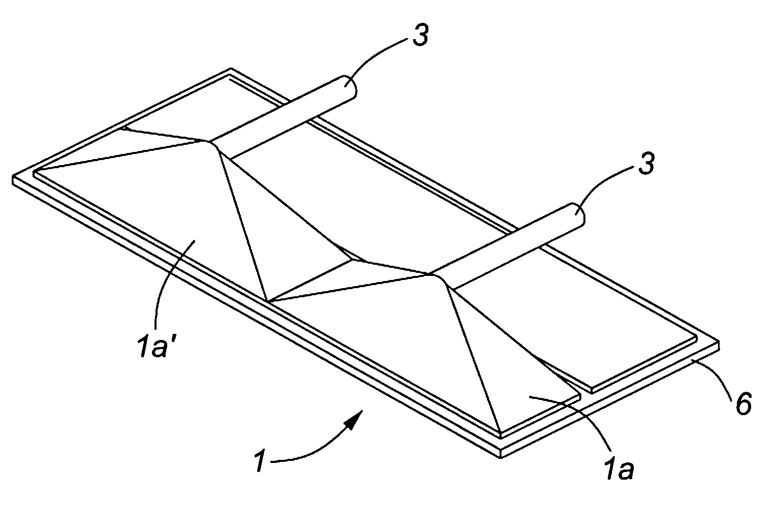
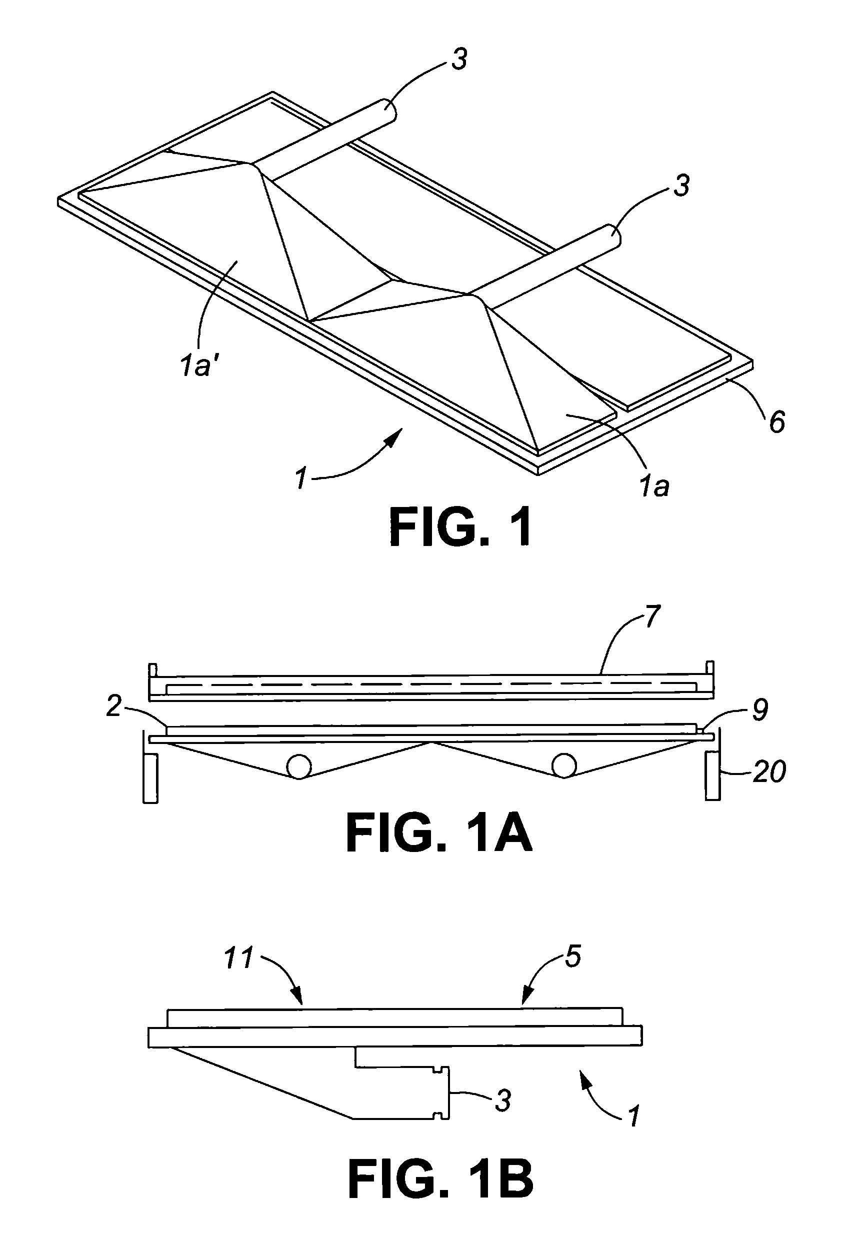
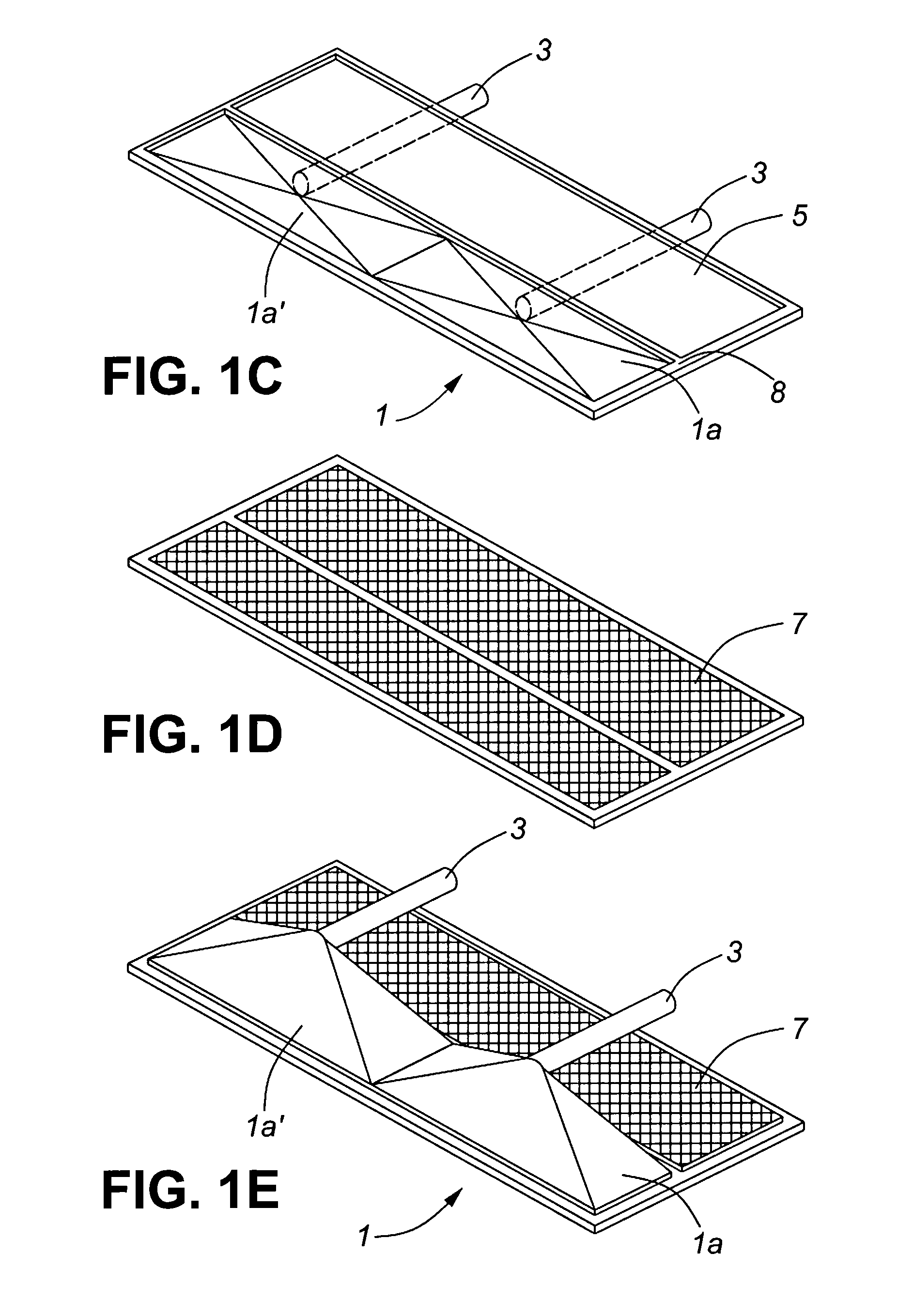
FIELD OF THE INVENTION[0001]The invention describes systems and methods for separating fluids from drill cuttings. Specifically, the invention relates to shakers that incorporate a vacuum system and methods of operating such systems to effect a high degree of fluid separation. The system and methods are effective across a variety of screen sizes, vacuum flows and vacuum designs.BACKGROUND OF THE INVENTION[0002]The loss of drilling fluids presents several technological and cost challenges to the energy exploration industry. These challenges generally include the seepage losses of drilling fluids to the formation, the recovery of drilling fluids at surface and / or the disposal of drilling detritus or cuttings that are contaminated with drilling fluid. In the context of this description, “drilling fluid” is both fluid prepared at surface used in an unaltered state for drilling as well as all fluids recovered from a well that may include various contaminants from the well including water...

Claims


Application Information

Patent Timeline
IPC IPC(8): F26B20/00F26B5/12
CPCB01D33/0353B01D2201/204F26B20/00B07B13/16F26B5/12B07B1/28E21B21/06E21B21/063B01D19/0073B01D33/0376B01D33/801E21B21/065B01D33/745
Inventor POMERLEAU, DANIEL GUY
Owner FP MARANGONI INC
Why Eureka
Try Eureka