Method for operation of dust collection device, and dust collection device

Inactive Publication Date: 2013-03-28
MITSUBISHI HEAVY IND MACHINERY SYST LTD
View PDF9 Cites 25 Cited by
  • Summary
  • Abstract
  • Description
  • Claims
  • Application Information

AI Technical Summary

Benefits of technology

[0035]According to the present invention, because a hammering mechanism is unnecessary, the configuration of the pre-charging unit can be simplified. Further, even when

Problems solved by technology

Formation of this dust layer causes low pressure loss, and fine particles cohere to the coarse particles.
T

Method used


Image

  • Method for operation of dust collection device, and dust collection device
  • Method for operation of dust collection device, and dust collection device
  • Method for operation of dust collection device, and dust collection device

Examples


first embodiment

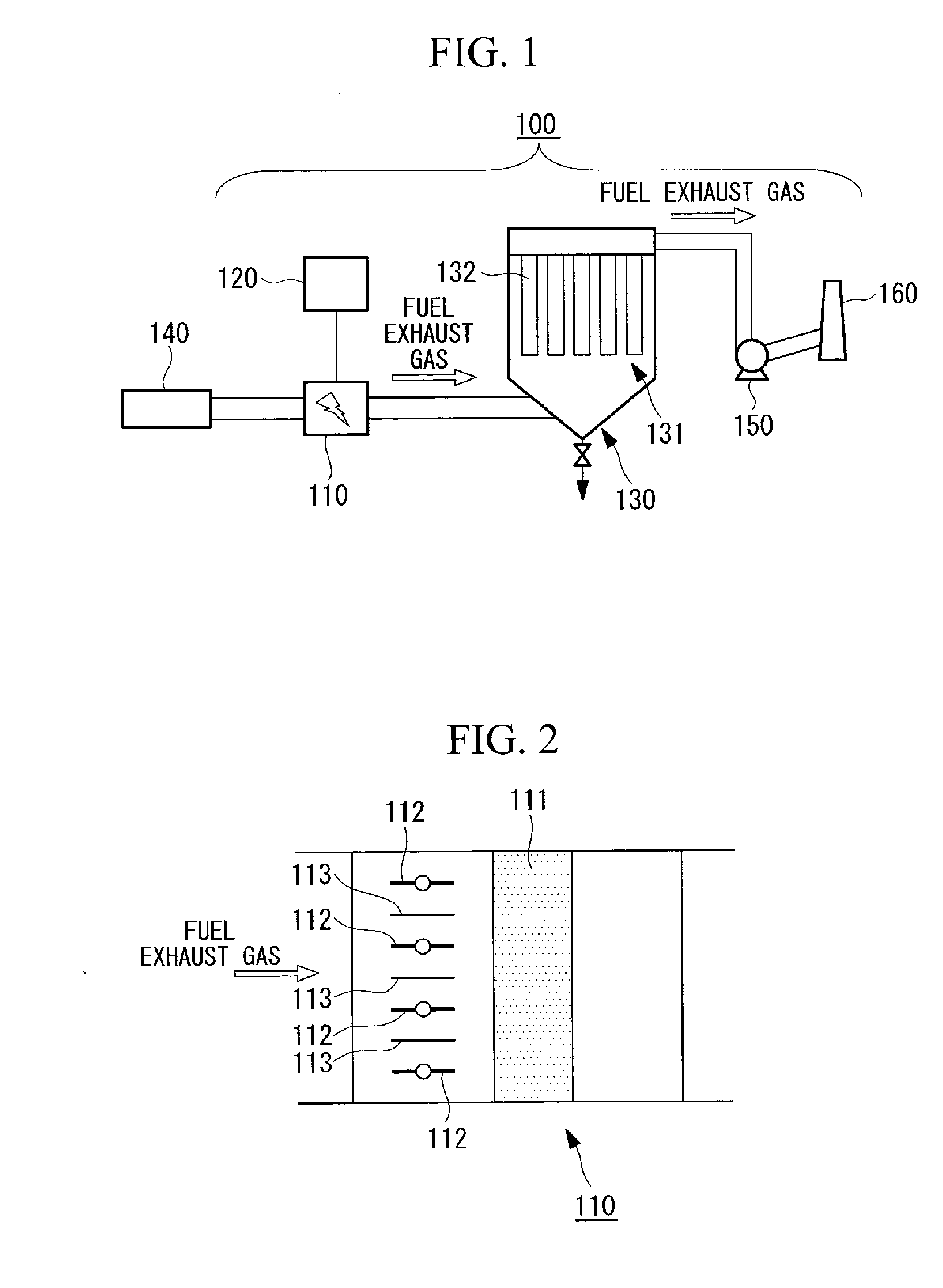
[0051]FIG. 1 is a schematic view of a dust collection device according to this embodiment. A dust collection device 100 is installed in a flue gas duct positioned downstream from a boiler (combustion furnace) 140, and comprises a pre-charging unit 110 and a bag filter 130, with the pre-charging unit 110 positioned upstream from the bag filter 130. An induced draft fan 150 and a chimney 160 are disposed in a flue gas duct downstream from the bag filter 130.

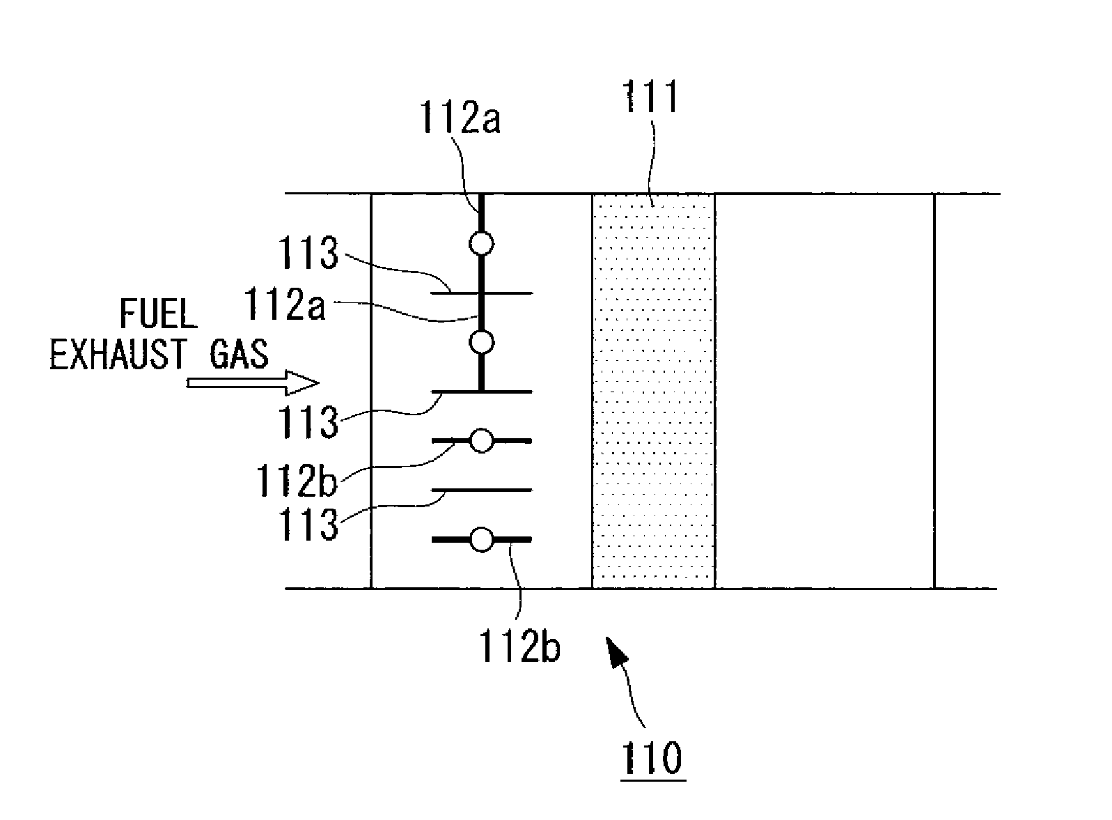
[0052]FIG. 2 is a schematic view of the pre-charging unit of the dust collection device. The pre-charging unit 110 comprises an electrode section 111 thereinside. The pre-charging unit 110 also comprises a gas flow rate control device that adjusts the flow rate of the gas flowing through the pre-charging unit 110 to a prescribed value. In this embodiment, the gas flow rate control device comprises a gas flow path modification unit 112, which is provided at at least one of the gas inlet side and the gas outlet side of the pre-chargi...

second embodiment

[0078]Next is a description of a second embodiment.

[0079]If discharge is continued during the electrode cleaning operation described above, then because the dust is charged, removal of the dust from the electrode surfaces becomes difficult. Accordingly, in this embodiment, either prior to the commencement of electrode cleaning (namely, closing of the dampers) or during the electrode cleaning, the control unit 120 may stop the current supply from the power source to the discharge electrodes, or to the internal electrodes and the surface electrodes, thereby stopping the discharge. In this case, during the period while the cleaning is performed, the dust passing through the pre-charging unit 110 does not undergo charging and cohesion, but rather flows into the dust chamber 131 of the subsequent bag filter 130 in a state that still includes very fine dust. Because dust that has previously undergone charging and cohesion is already trapped on the filter cloth 132, the uncharged dust is t...

third embodiment

[0085]In this embodiment, the difference in pressure loss achieved by performing charging control in the pre-charging unit is described. This embodiment is applied to both a dust collection device that employs the step of removing dust by increasing the gas flow rate, as described in the first and second embodiments, and a dust collection device that does not employ the dust removal step. With the exception that the mechanism for increasing the flow rate is optional, the structures of the devices are the same as those described above.

[0086]First is a description of the differences between no charging, continuous charging, and on-off charging control.

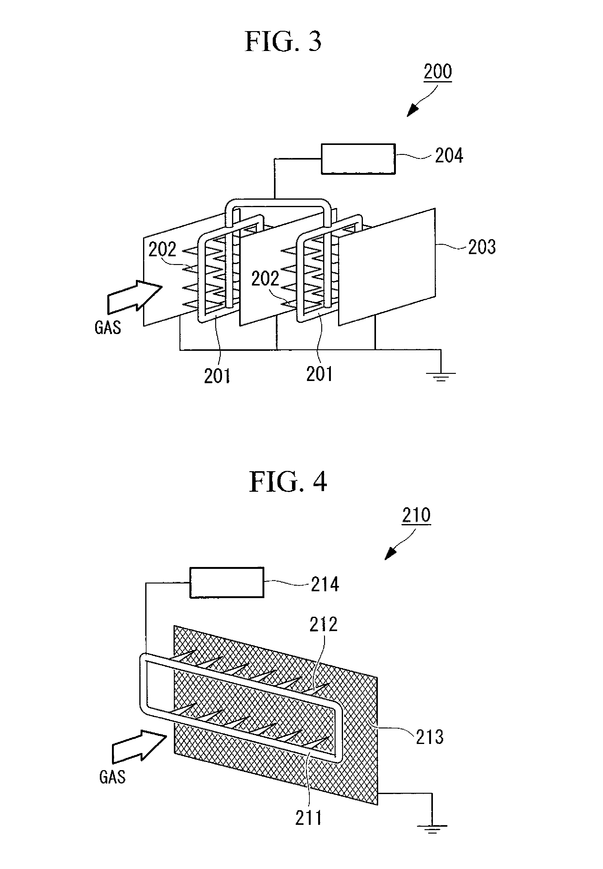
[0087]FIG. 11 is a comparative diagram which compares, for a device that employs the electrode configuration illustrated in FIG. 3 and uses the pre-charging unit to charge the dust, the case (c) in which the voltage is varied by using on-off charging control, and the cases (a and b) in which no charging or continuous charging respectivel...


PUM

PropertyMeasurementUnit
Speedaaaaaaaaaa
Flow rateaaaaaaaaaa
Electrical resistanceaaaaaaaaaa

Abstract

A method for operating a dust collection device by reducing the adhesion of high-resistance dust while performing stable charging, with minimal pressure loss and high efficiency. The dust collection device comprises a pre-charging unit and a bag filter in a flue gas duct through which a gas flows, with the pre-charging unit disposed upstream from the bag filter, wherein the pre-charging unit comprises electrodes that charge the dust, a power source that supplies electric power to the electrodes, and a gas flow rate control device that adjusts the flow rate of the gas flowing through the pre-charging unit to a prescribed value. The method comprises a step of charging the dust by applying a voltage from the electrodes to the dust, and a step of removing the dust adhered to the electrodes by increasing the flow rate of the gas flowing through the pre-charging unit.

Description

TECHNICAL FIELD [0001]The present invention relates to a dust collection device that removes dust contained within a gas, and a method for operating the device.BACKGROUND ART[0002]Conventionally, bag filters comprising a filter cloth have been installed for removing dust (particulate matter) contained within gases. Examples of the gases include the exhaust gases generated upon combustion of coal or fuel oil, and air. The aforementioned bag filters are installed within the flue gas ducts of industrial combustion facilities such as coal-burning and fuel oil-burning power generation plants and incinerators, and are also installed in the vicinity of devices that generate dust, for use as dust collection devices that collect environmental dust.[0003]A pre-charging unit is sometimes installed in the flue gas duct upstream from the bag filter. The pre-charging unit comprises a charging unit composed of a discharge electrode and a grounding electrode which generates a corona discharge that ...

Claims


Application Information

Patent Timeline
IPC IPC(8): B03C3/80B03C3/017
CPCB01D46/02B01D46/50B03C3/08B03C3/09B03C3/155B03C3/41B03C3/366B03C3/68B03C2201/10B03C3/0175B03C3/80B03C3/363
Inventor TOMIMATSU, KAZUTAKAKATO, MASAYANAMBA, AKIYOSHIUEDA, YASUTOSHI
Owner MITSUBISHI HEAVY IND MACHINERY SYST LTD
Why Eureka
Try Eureka