System and method employing variable size mechanical binding elements in virtual rendering of a print production piece

Inactive Publication Date: 2013-03-28
XEROX CORP
View PDF6 Cites 16 Cited by
  • Summary
  • Abstract
  • Description
  • Claims
  • Application Information

AI Technical Summary

Benefits of technology

[0010]Thus, the printing industry is always looking for ways to improve how it conducts business. Of particular interest are ways to reduce production costs and improve efficiency. The system and methods disclosed herein transform the current production print practice by creating an easy to use document production visualization system.
[0011]The existing technologies that produce virtual renderings of a finished print piece are generally limited to providing only a two dimensional perspective. There are a few applications that provide a 3D rendering, but they are commonly implemented as a vector graphics-based animation application with full-screen navigation interfaces, graphic illustrations, and simple interactivity in an antialiased, resizable file format that is small enough to stream across a normal modem connection (e.g., FLASH™) or high-level computer programming languages that allow small application programs to be downloaded from a server to a client along with data that each program processes (e.g., JAVA™) and may require users to install undesirable plug-ins or run special applications. Thus, there exists a need for a system architecture that allows for a true 3D rendering in a browser with the ability to utilize various input formats and components (e.g. JDF, PDF), output rendering engines (e.g. JAVA3D™, FLASH™, Silverlight™, HTML5, SVG) and provide for flexibility of deployment (e.g. stand-alone applicatio

Problems solved by technology

The existing technologies that produce virtual renderings of a finished print piece are generally limited to providing only a two dimensional perspective.
There are a few applications that provide a 3D rendering, but they are commonly implemented as a vector graphics-based animation application with full-screen navigation interfaces, graphic illustrations, and simple interactivity i

Method used


Image

  • System and method employing variable size mechanical binding elements in virtual rendering of a print production piece
  • System and method employing variable size mechanical binding elements in virtual rendering of a print production piece
  • System and method employing variable size mechanical binding elements in virtual rendering of a print production piece

Examples


Embodiment Construction

1.0 System and Architecture

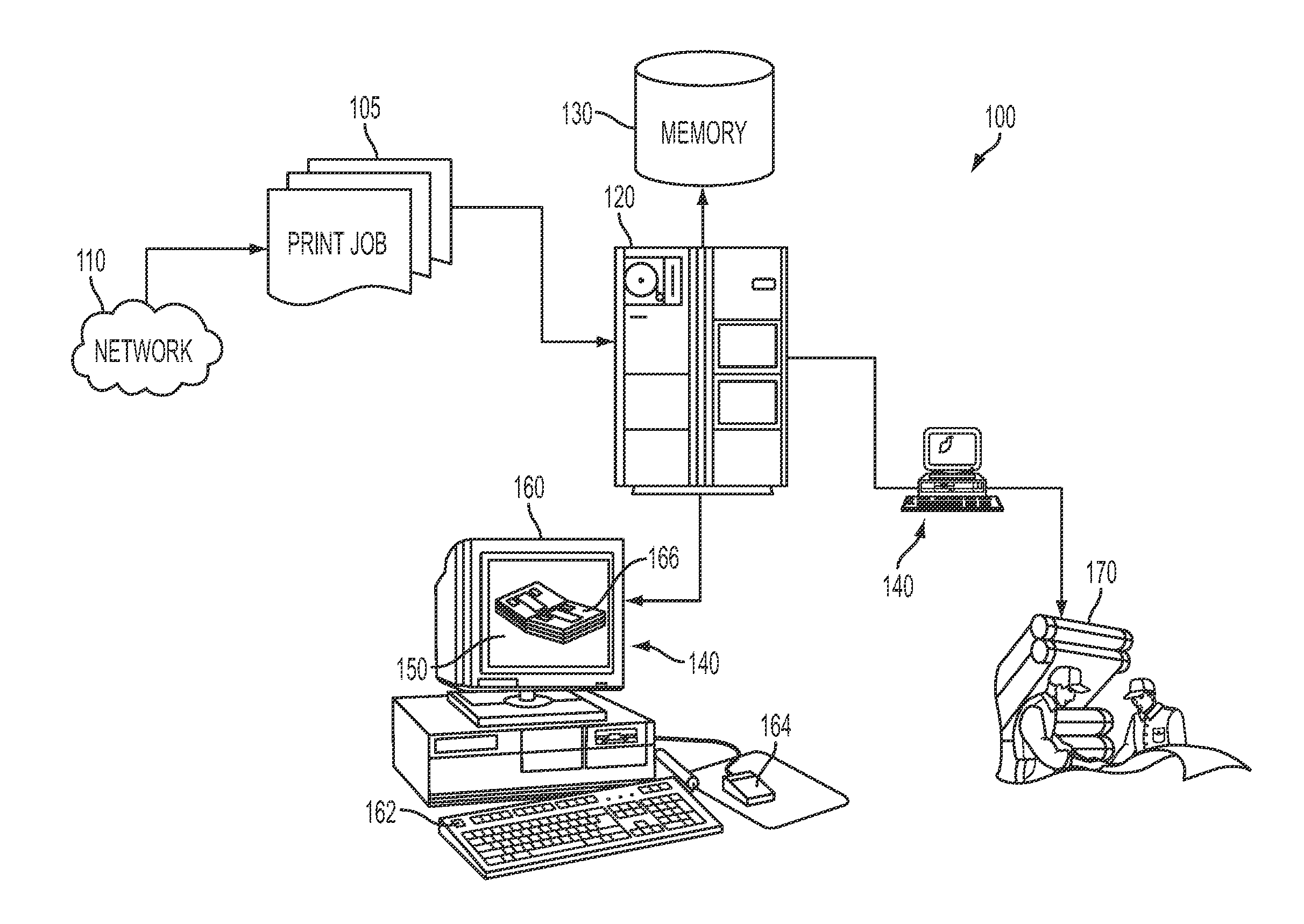
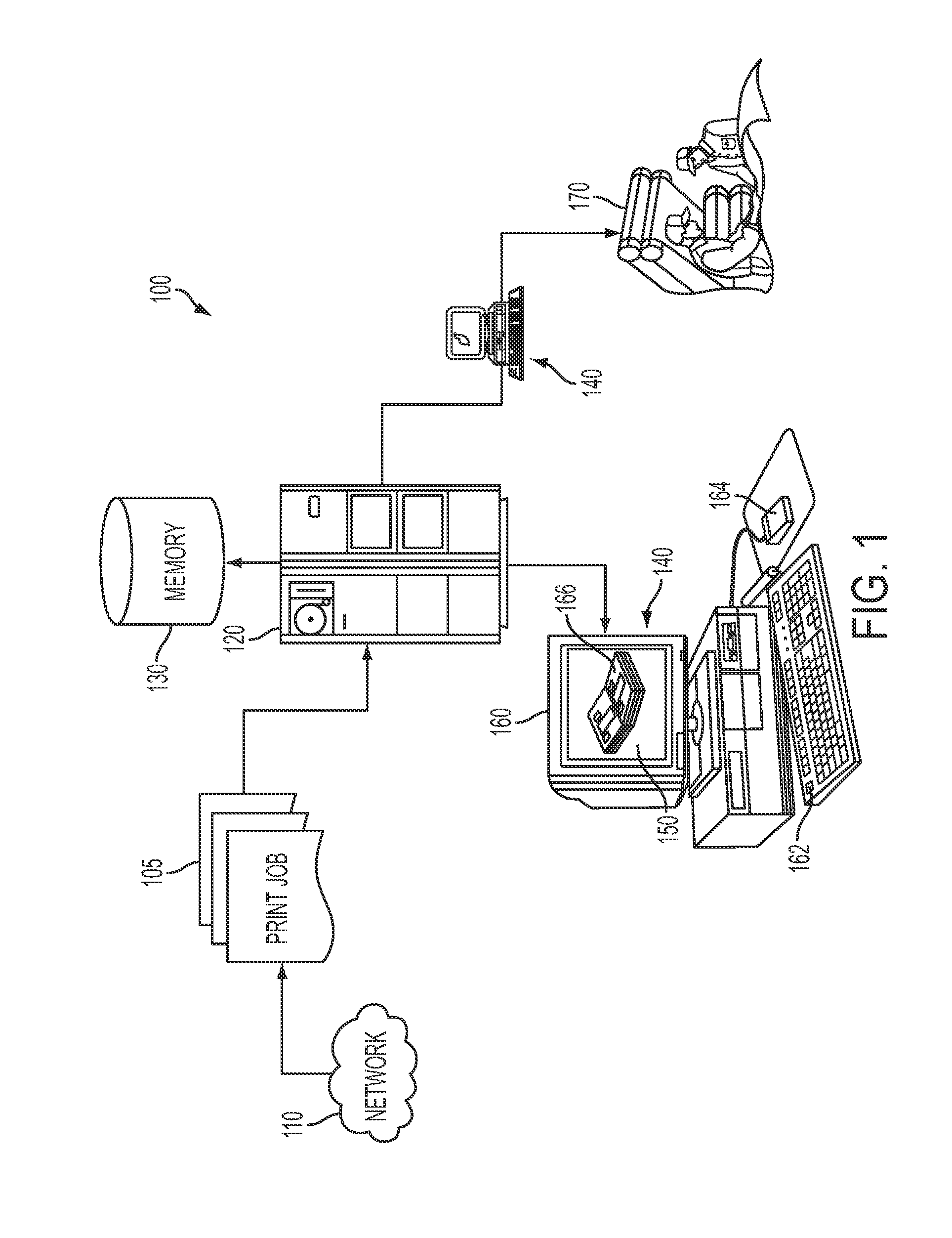
[0070]In FIG. 1 there is depicted an exemplary system 100 upon which the following disclosure and methodology may be implemented. It is to be understood that certain aspects of the system would operate in accordance with pre-programmed instructions stored on various media and used to operate a local or networked computer system to carry out such features, and perhaps across a plurality of interconnected computers at a time. Such a system might include a commercially available personal computer with appropriate graphics rendering capability, that can also be associated with a computer storage medium (e.g., removable disk or similar portable media, RAM, ROM, and other non-transitory means for storing digital information that may be at least read by a computer) or similar memory devices and where the system is accessible, perhaps via an Internet or intranet for submission of print jobs. It is also contemplated that one or more aspects of the system may be imp...


PUM


Abstract

A system and method for a pre-print, three-dimensional virtual rendering of a print piece is disclosed. A plurality of modular/pipelined architectural layers are managed, operated, and organized by a controller. A product definition is provided to a job ticket adaptation layer where it is transformed into a physical model. The physical model is then transformed into a display model via the product model layer. The display model is transformed into a scene that can be displayed on a graphical user interface as a three dimensional virtual rendering by a rendering layer, where the rendering includes one or more binding elements to satisfy the product definition. The modularity further enables different product description formats to be supported by only altering the job ticket adaptation layer, and that different graphics rendering engines can be supported by altering only the rendering layer.

Description

CROSS-REFERENCE TO RELATED APPLICATIONS[0001]Cross reference is made to the following application, which is hereby incorporated by reference in its entirety for its teachings, U.S. Patent Application Publication No. 2006 / 0114490, U.S. Ser. No. 11 / 001,431, entitled “SYSTEM AND METHOD FOR DOCUMENT PRODUCTION VISUALIZATION,” filed Dec. 1, 2004 by Robert J. Rolleston. Cross reference is also made to the following concurrently-filed applications that are each hereby incorporated by reference in their entirety:[0002]a) Atty Docket No. 20090523-US-NP, for a SYSTEM ARCHITECTURE FOR VIRTUAL RENDERING OF A PRINT PRODUCTION PIECE, by R. Rolleston et al. filed concurrently herewith;[0003]b) Atty Docket No. 20090600-US-NP, for a SYSTEM AND METHOD EMPLOYING 3D MODELS IN VIRTUAL RENDERING OF A PRINT PRODUCTION PIECE, by R. Rolleston et al. filed concurrently herewith;[0004]c) Atty Docket No. 20091255-US-NP, for a SYSTEM AND METHOD EMPLOYING SEGMENTED MODELS OF BINDING ELEMENTS IN VIRTUAL RENDERING...

Claims


Application Information

Patent Timeline
IPC IPC(8): G06T15/00
CPCG06T19/20G06T2200/24G06F3/1285G06F3/1256G06F3/1205G06T15/00
Inventor ROLLESTON, ROBERT J.NATARAJAN, AANANDNEGINHAL, MAHESH
Owner XEROX CORP
Why Eureka
Try Eureka